

lookforjoe
-
Posts
13,471 -
Joined
-
Last visited
-
Days Won
92
Content Type
Profiles
Forums
Gallery
Blogs
Downloads
Events
Store
Bug Tracker
Posts posted by lookforjoe
-
-
Nice work, Matt.
That fuel rail looks awfully familiar

Regarding the JPT terminal housings (4pole for original coil) - since you only need 2 wires, you CAN buy the two pole male # 106462-1. TE Connectivity "Automotive Connectors FASTIN-FASTON 2P HSG" The 2 pole female is 282189-1
I use them often & get them from Mouser. The 'Tabs" (male pins) come in a range of AWG crimp sizes, but you can remove the originals from the 4 pole & reuse the factory tabs - there is an awesome tool that does remove the male & female JPT terminals used all over the engine harness.
-
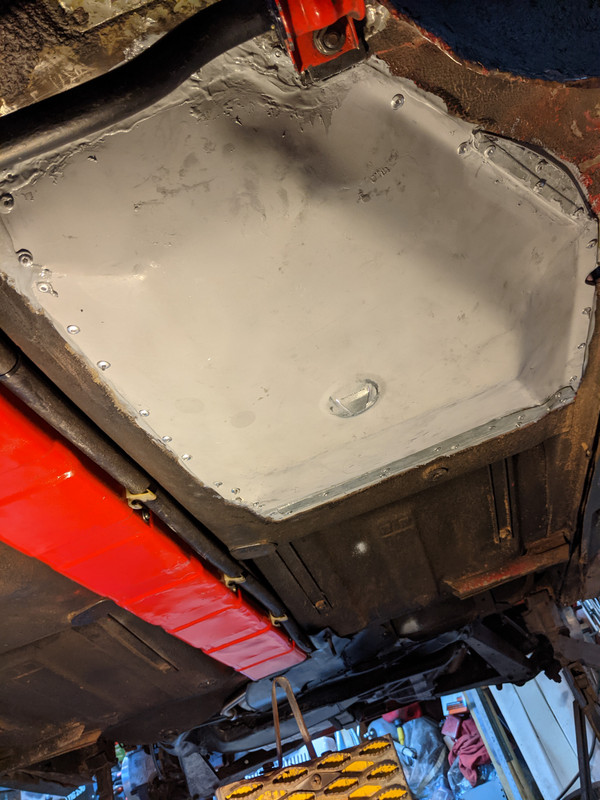
It's been bloody cold here in my part of NY, along with some mild health issues, I haven't been doing much on the car - I'm lucky if I get the metal of the body up to 40ºF, so it sucks all the heat out of me leaning on it or under it to work.
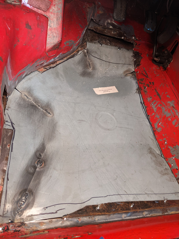
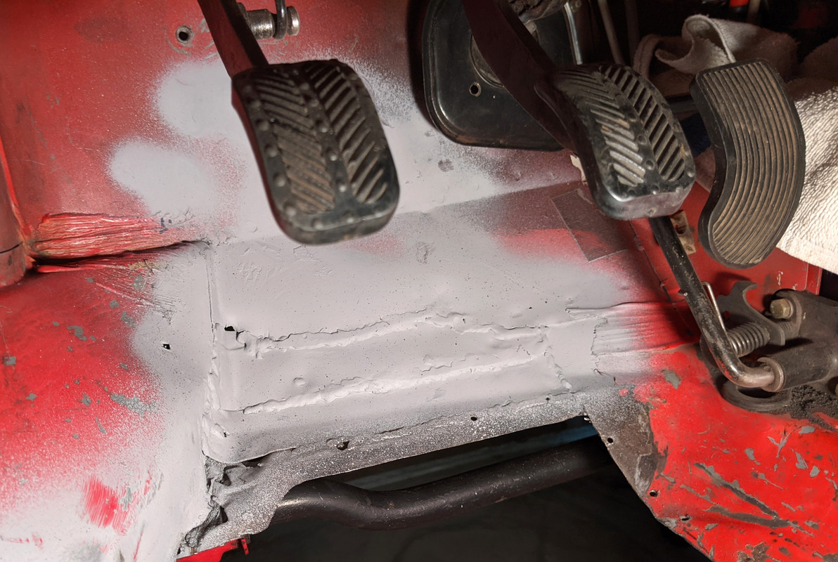
Anyway, I did have time to get the floor pan fitted. stripped all mating surfaces (about 1" overlap) Rough sanded for adhesion with the Fusor 2 part body epoxy. Cut the drain hole to match the factory drains in the three other areas. This product is very low odor and has about 90min work time - so not difficult to work with for fiddly panels like this
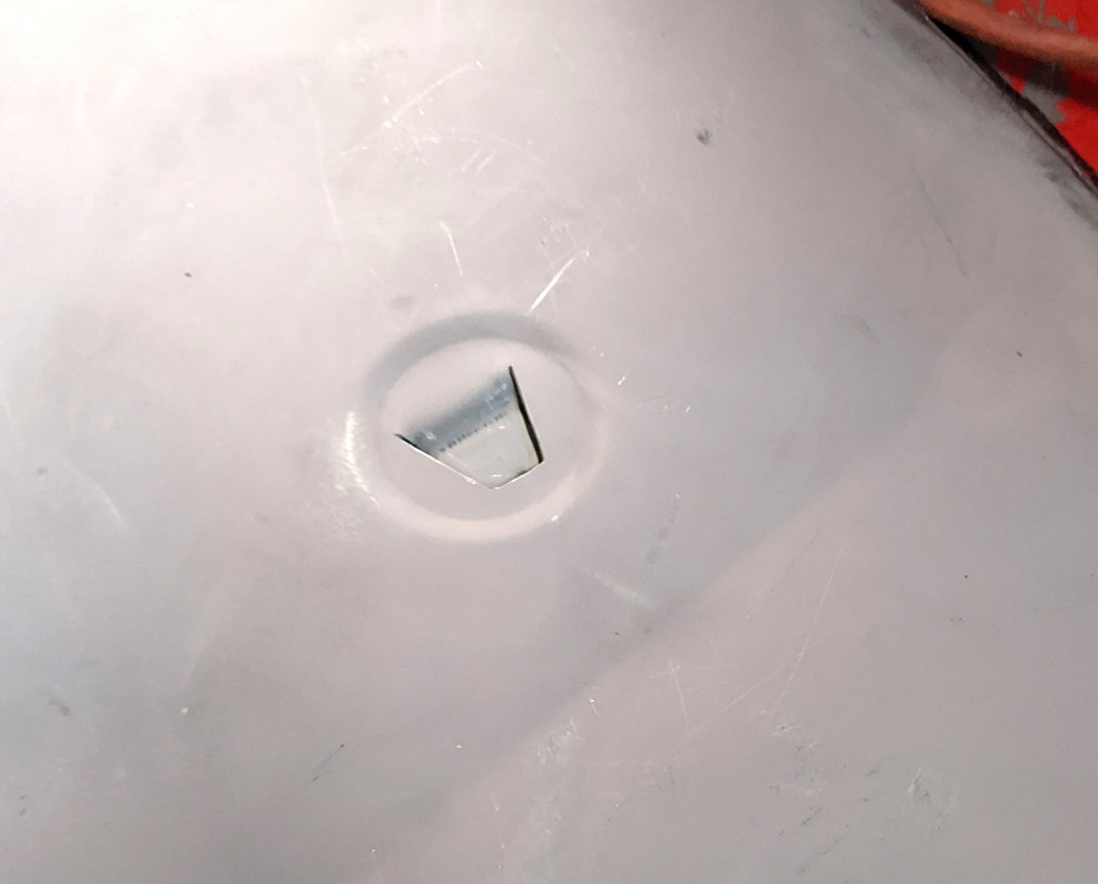
put a schmear of epoxy over all the mating surfaces first, as they recommend, then approx 1/4" bead on one of the mating surfaces

Installed. Setup times are all rated at ambient temp -around 70ºF - so it will take probably twice as long (at least) in the unheated garage temps of around 20ºF. Once it's cured, I'l grind off all the rivets ends on the inside & caulk the seams with a good paintable body caulk
-
 1
1
-
-
2 hours ago, apeacock said:
The black porches ones and the same discs are still going strong ;D
I may elect to change the discs and pads this year as the e-brake doesn't work so great.Nice! They really are overkill - but that does mean pads & rotors last much longer!
You have CEIKA up front, correct?
-
On 1/27/2021 at 9:13 AM, flyfishing3 said:
nice. 6 pot.
need adapters to work?
Yes, you buy the kit - offset adaptors (dependent on choice of rotor), calipers, rotor rings & hubs, new lines
-
1
-
-
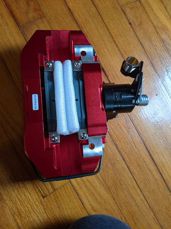
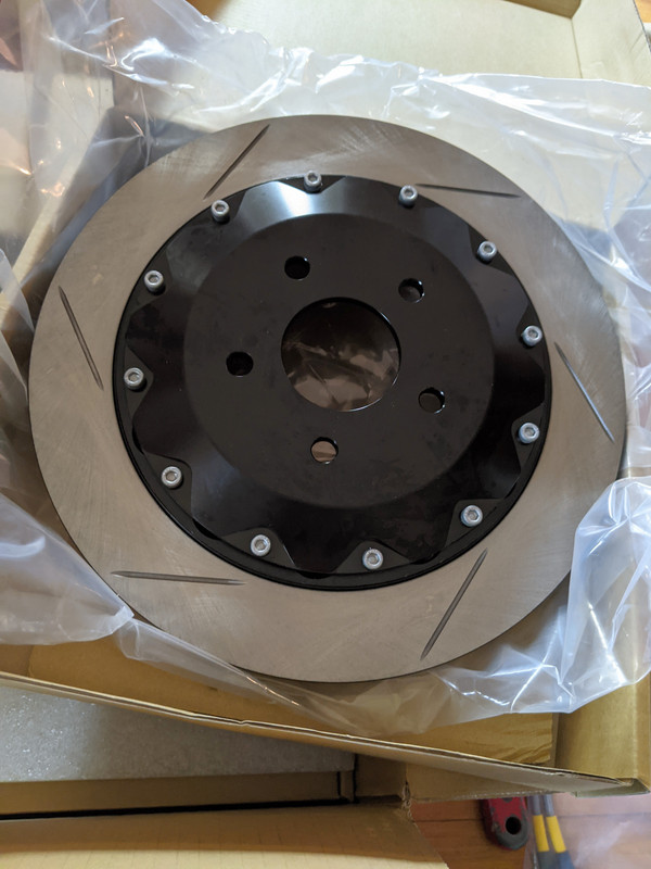
New calipers for the C30 - the originals (about 8 years old now) were intended for the V70 - the black doesn't go so well on a black car.
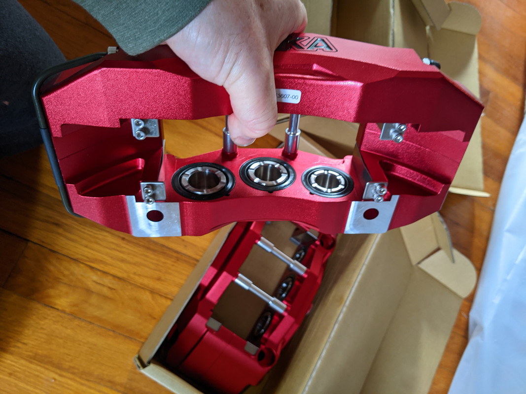
Main reason was this - revised design for the eBrake

New wheels (17") for my snows for next year - my Enkeis are kinda beat up now

-
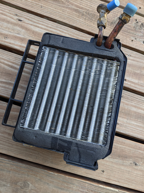
Dismantled & refurbished the HVAC box

cleaned all the sections

checked brushes, bearings, etc
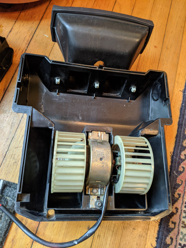
Made new Neoprene gaskets for the Evaporator
Box to body seal

Center vent housing seal

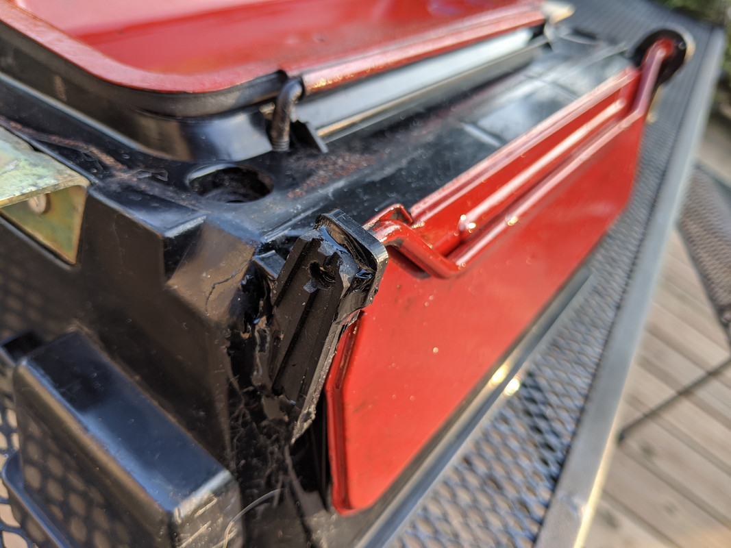
Removed and refurbished the flaps - the upper one had a seized hinge, which cracked the main housing by stressing the recirc door

repaired the hinges
Made the recirc control removable - drilled out the rivets & used M5 rivnuts instead
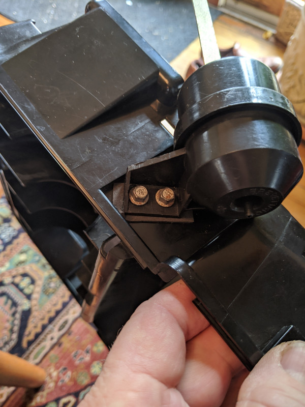
Haven't put it back in yet, as complete access to the floor pan for repair is easier with that center area unobstructed. I'v put this off for at least 6 years - so about time I deal with it

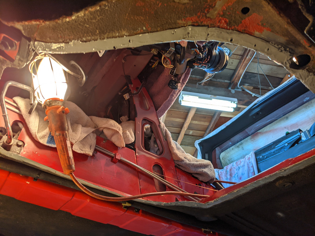
Start on cutting out the rot
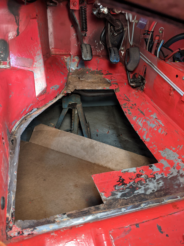
3 layers to deal with up here - not included in the replacement floor section
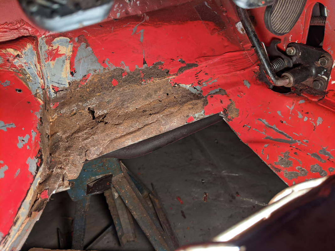
cut back
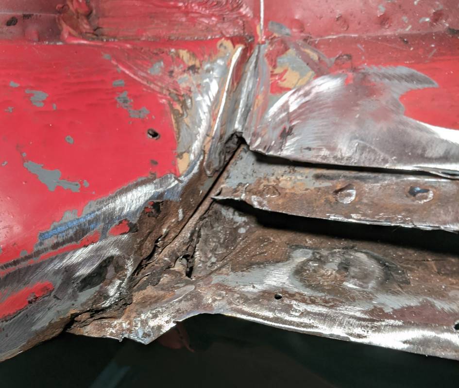

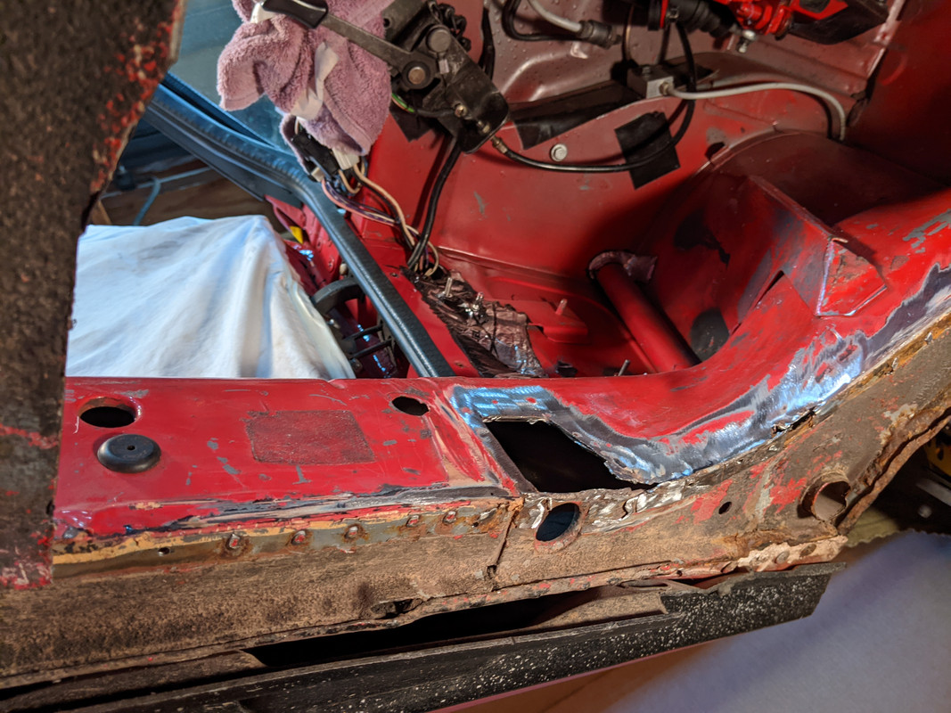
additional hole in the inner sill
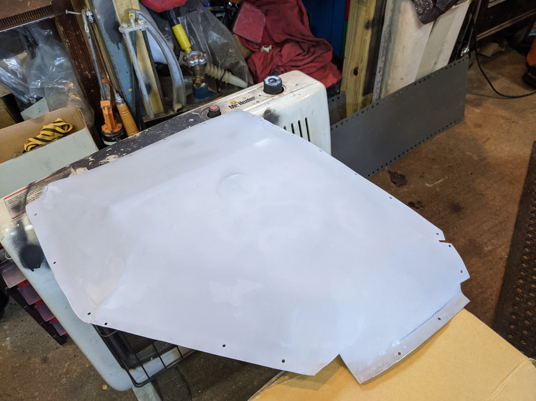
Replacement panel - not formed, but cut

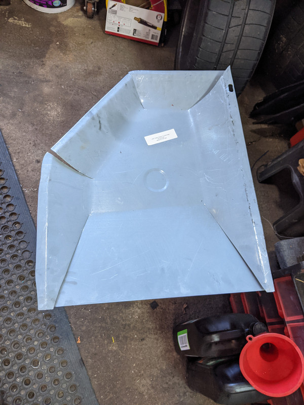
rough fit
rebuilding the bulkhead layers


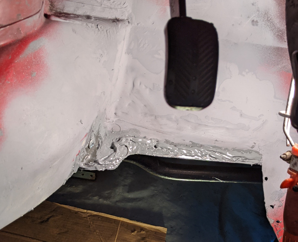
Sill patches


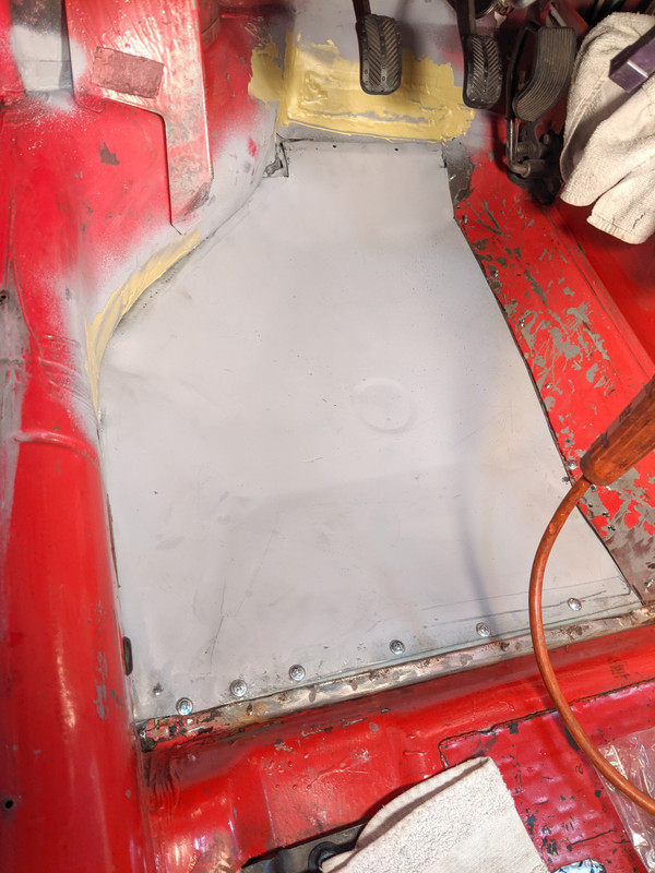
seams welded in floor section
test fit again, had to deal with some adjustments from distortion when welding the cuts
That's where I'm at - I hate rust repair. Getting there, slowly but surely.
-
Nice work, Matt! Yeah, I know from personal experience that cam cover vents create a nightmare when it comes to designing a catch can/ external drain back setup
You can get the large Oetiker clamps from McMaster, or Amazon. Using standard worm clamps is a bad idea - you can see where it has already dug into your silicone elbow...
-
Covered the dash top with 1/16" neoprene foam , then adhesive backed vinyl.


-
5
-
-
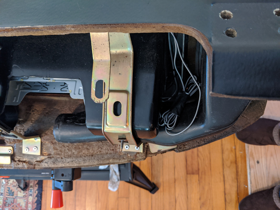
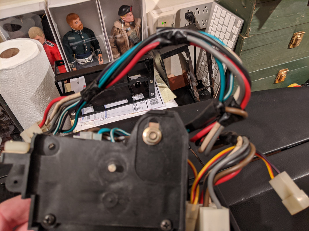
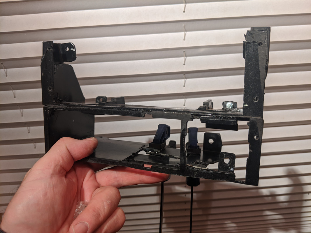
Been working on the dash wiring. Put the ductwork back in to check harness routing, had to rewire center console harness (again) to allow it all to be pulled back when servicing the console switch housing.

This is where I left off, temps dropped into the teens, too cold to work out there

Decided to work on the dash / cluster layout, since that I can do in the house & basement
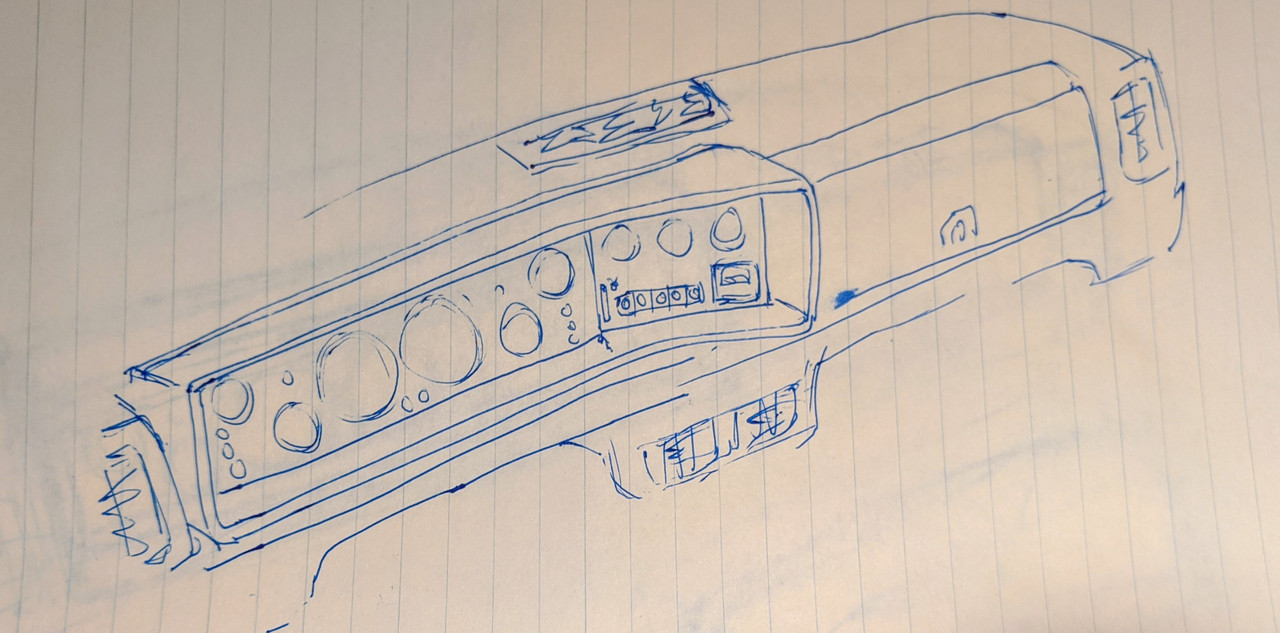
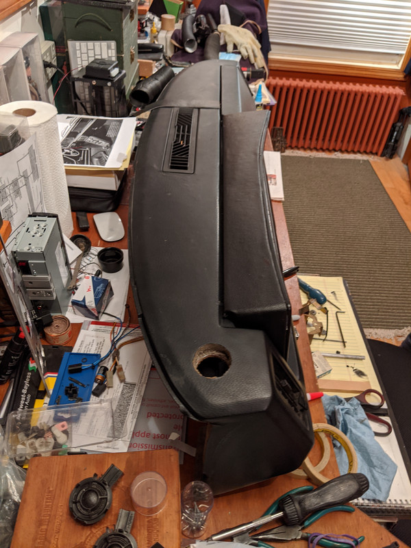
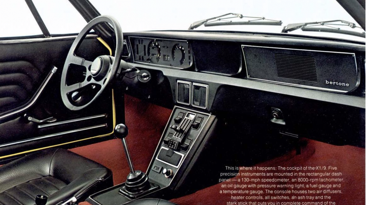
Went through several incremental revisions of the binnacle - which is a typical 80's Bertone layout - really boxy design.
When Bertone designed this revision, they moved the entire cluster several inches closer to the driver, which cuts off visibility of the gauges. They did this to allow for the AC side dash vents to pass behind. Sloppy work, as they could have spent time making the layout more efficient & not add so much space between the bulkhead & IPpass side
driver's side - you can see the offset of the fixed tube could have easily been angled to allow at a couple inches of more of additional space here


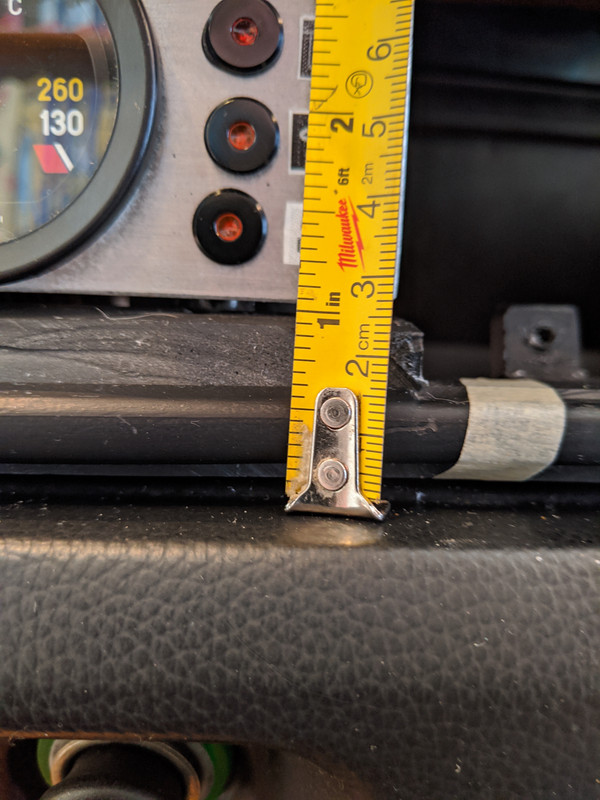
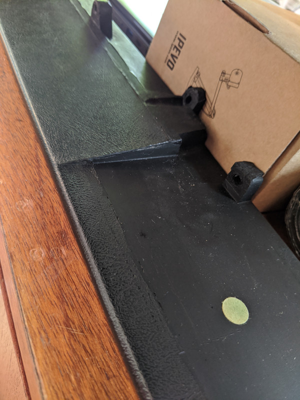
Depth from dash to center vent - this is where the AC panel has to fit, so space is more critical
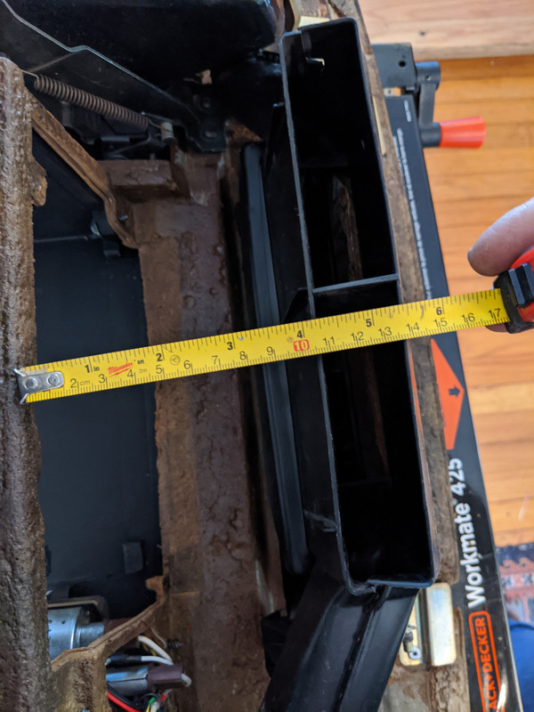
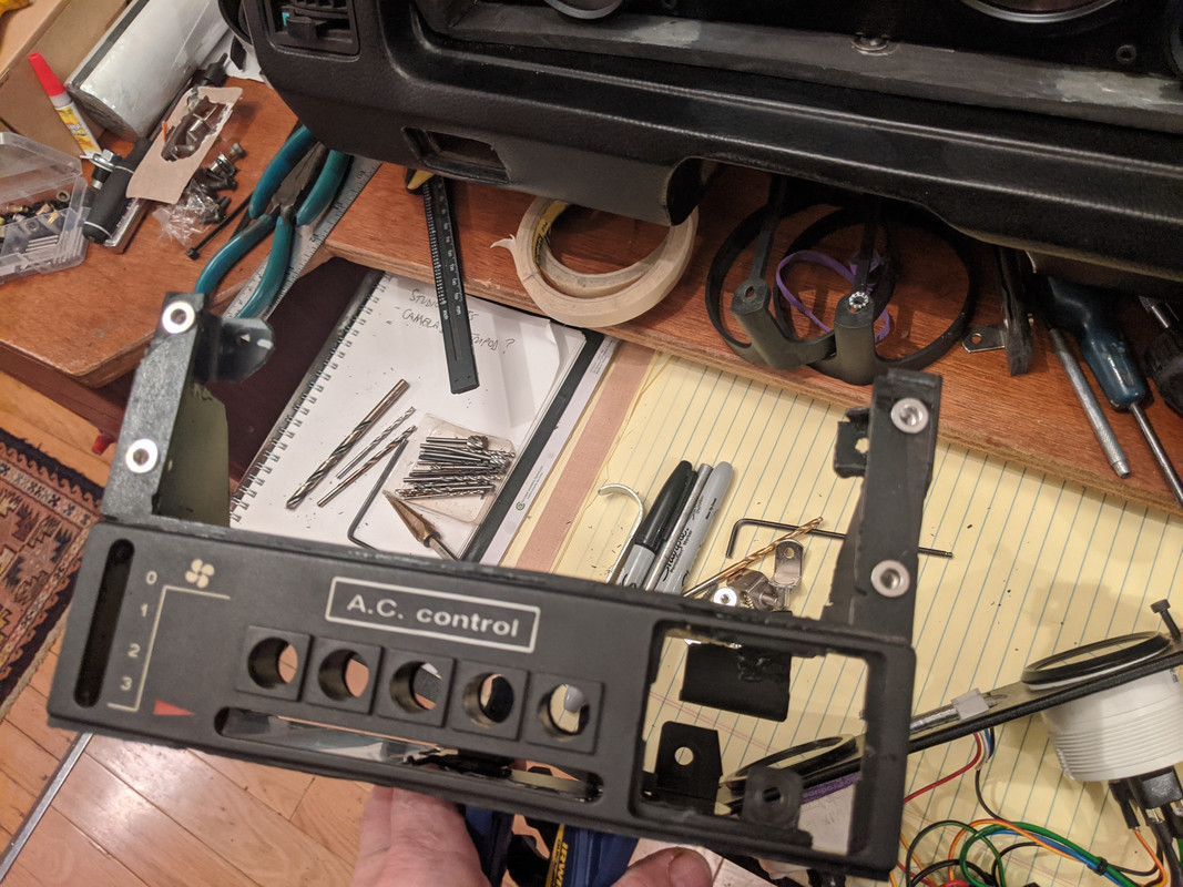
chopped a couple inches off the back of the control panel, to allow it to sit back and on an angle
Initial plan - eliminate some of the binnacle to reduce the overhang & angle the center panel toward the driver

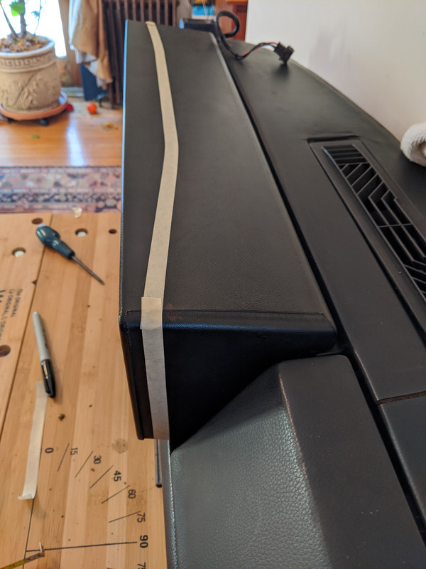
After 1st cuts - what I did was cut off the outer 1/2" lip of the binnacle first, to then attach it later once the work is done, hence the masking tape here
Comparison with original binnacle ( I cut up the spare from my parts car)
It appears the binnacle is solid rubber, or a rubber-compound, it cuts & smells just like old tires
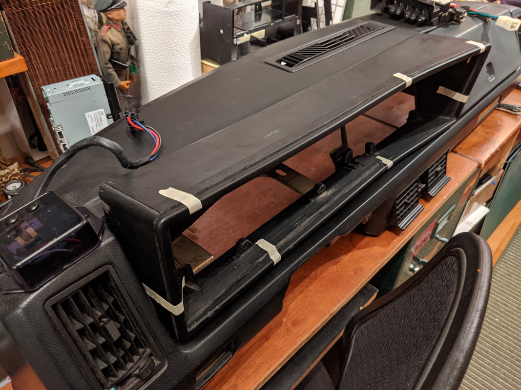
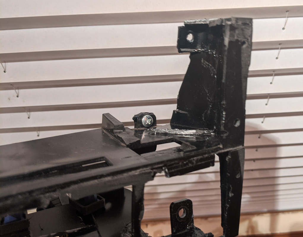
In cutting the binnacle, I also realized the cluster is elevated relative to the main dash, more obvious with the tapered exterior chopped back. This also doesn't help with gauge visibility, so I will address that also
you can see the 'ramp' here
chopped another section off the binnacle, and reduced the thickness of the lower ledge about 1/2" or so

Having dropped the cluster base, I had to remake the face panel for the gauges. Will be covered in vinyl
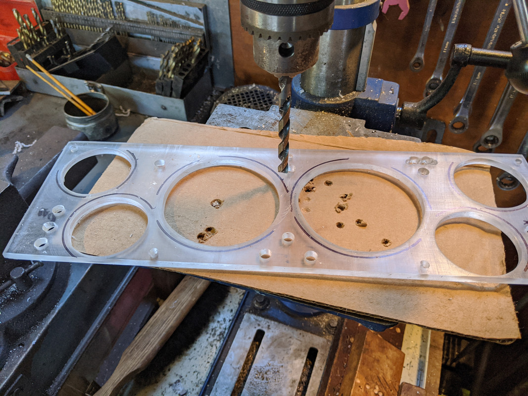
I had also chopped off all the stock cluster mounts, so I had to figure out a new system. What I ended up with, are those generic household shelving brackets - I drilled installed M4 rivnuts in them to secure the panel, and drilled through the rubber to utilize the existing peg mount
test on scrap - recessed the flange into the rubber

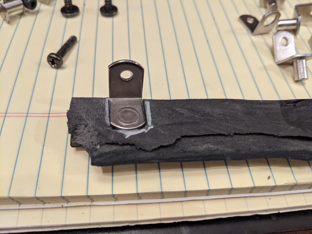
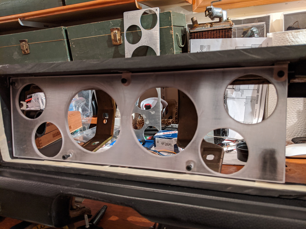
Five mounts in place - detail
seat-of-the-pants rebuild of the center support panel for the AC controls & extra gauges (used to be the radio location). Reversed locations - AC on bottom, gauges one top. I use ABS plumbing cement here. Patch it together to align with available dash mount points (3)
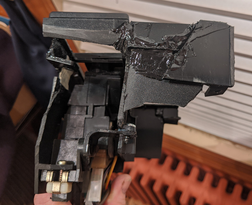

a little UPOL Gold to fill the imperfections where I chopped apron 3/8" off the top of the binnacle
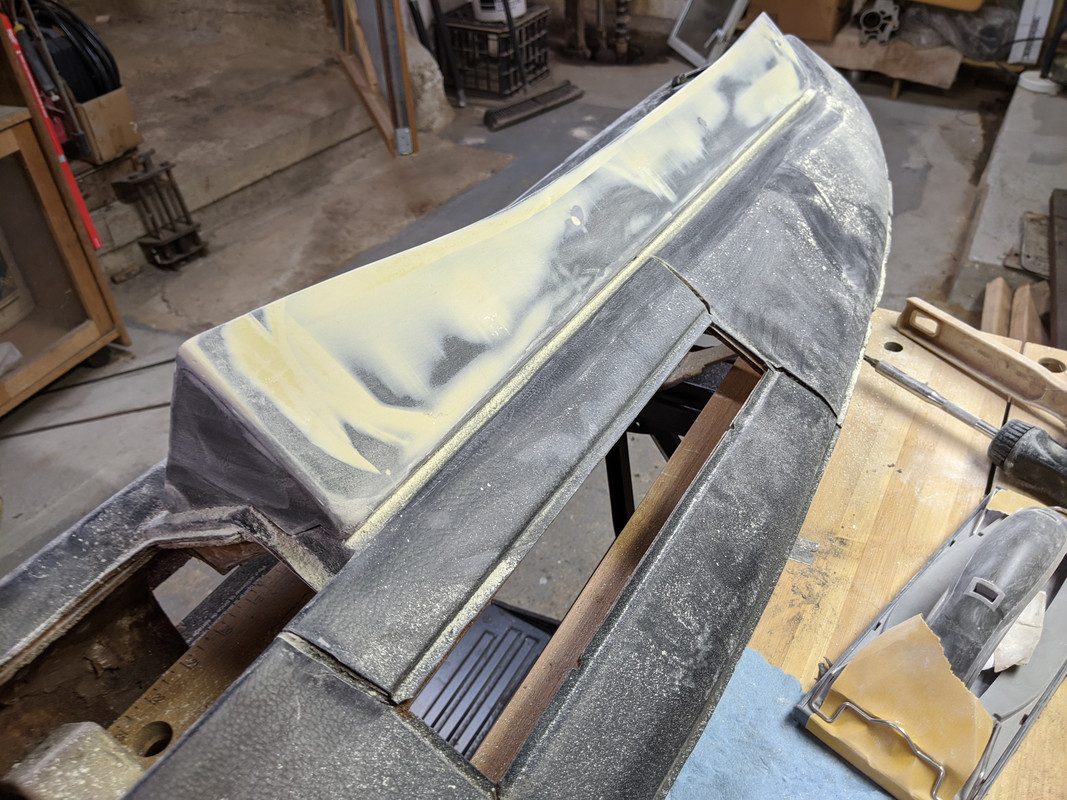
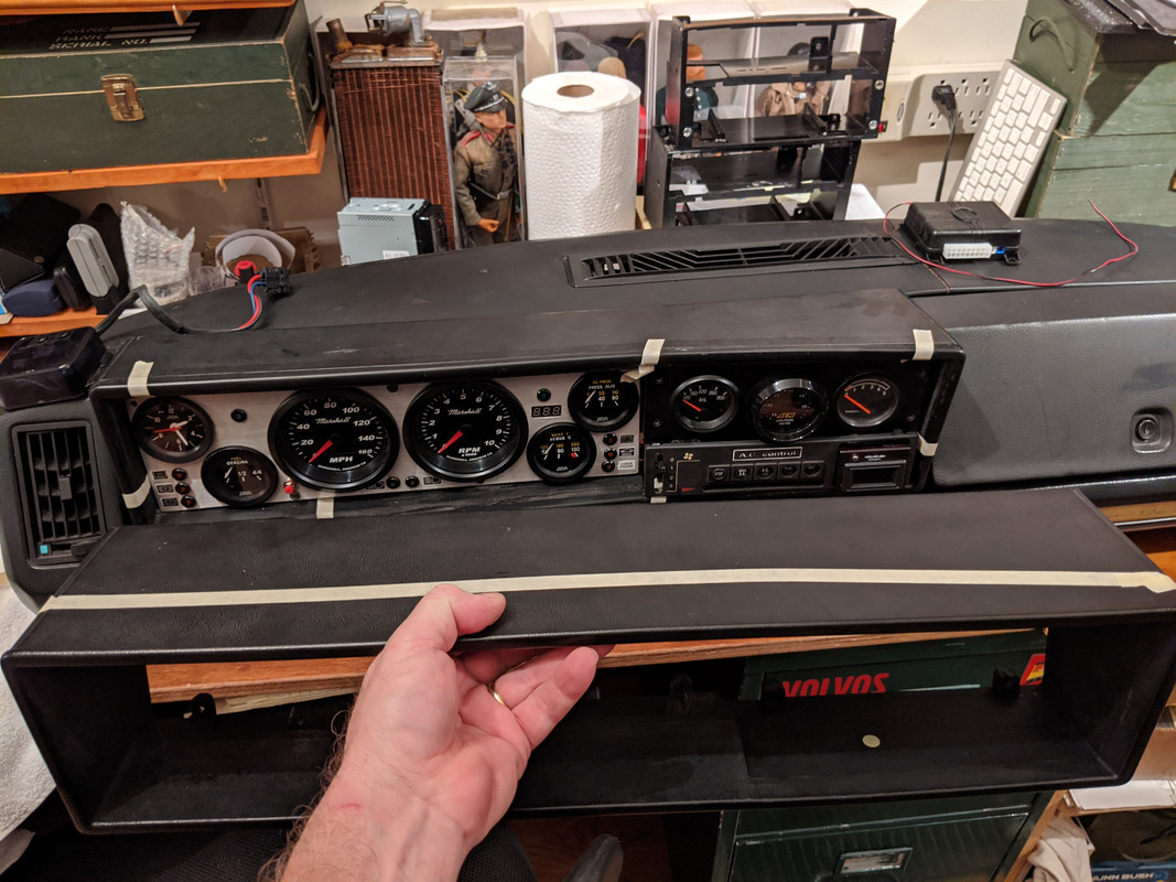
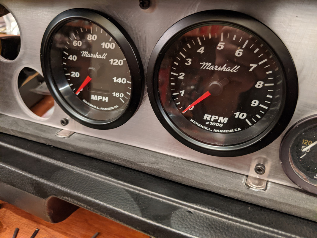
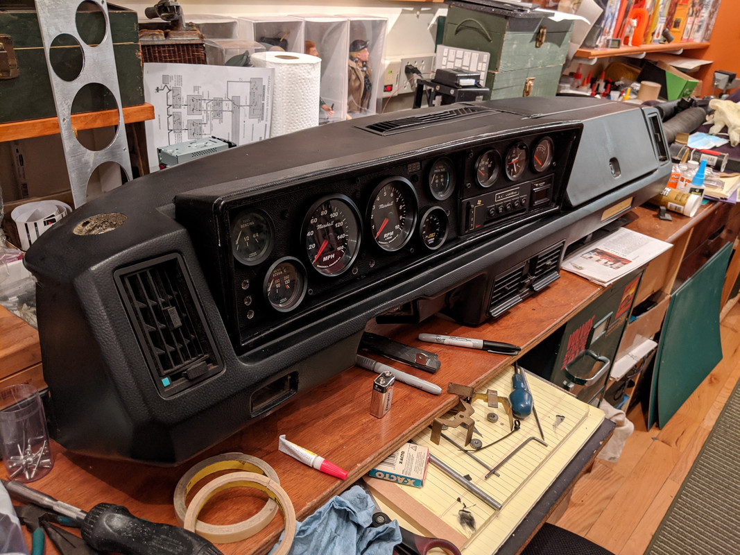
overall layout - moved WBO2 to main cluster, even with a modified VDO bezel, it still protrudes more than the old VDO & Veglia gauges (which I want to keep)
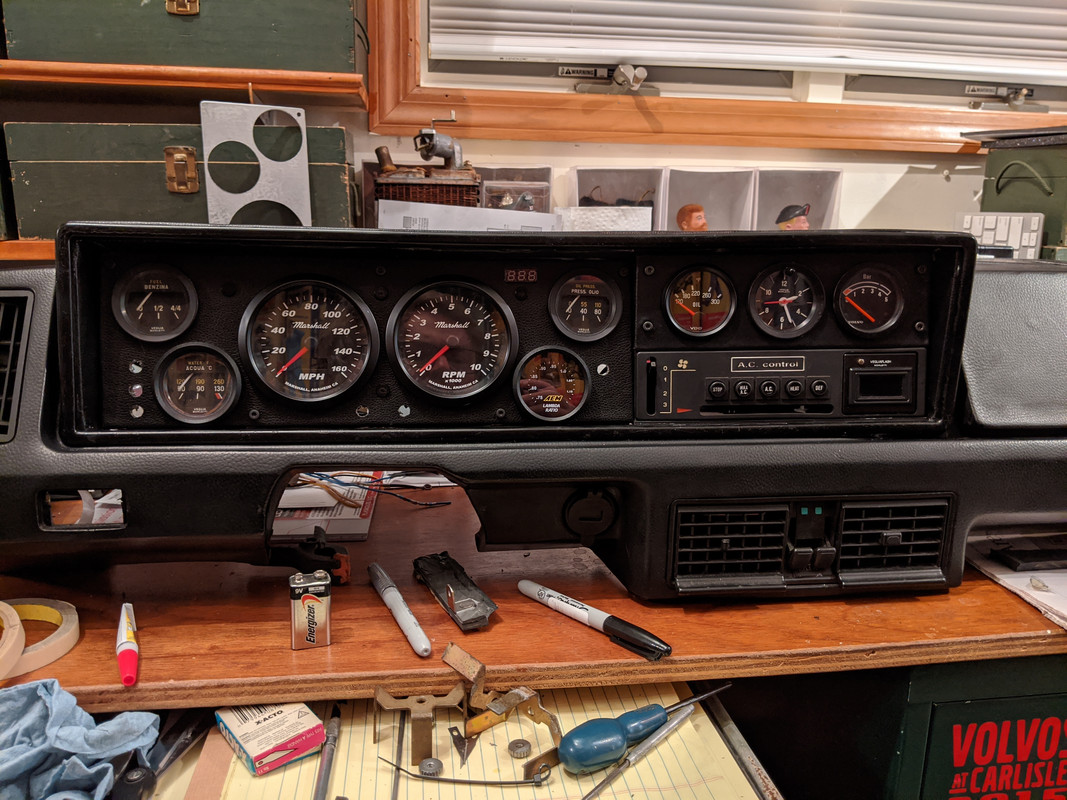
AlpineTech makes nice indicator bulbs, so no need for the descriptor labels I had previously

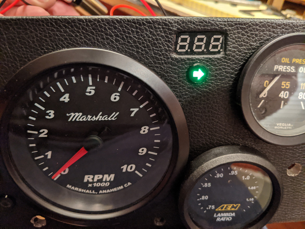
Happy with the overall flow now. I like the setback into the dash compared to the massive overhang of the stock layout.
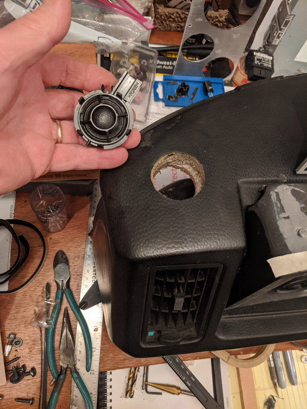
Just have to cut another tweeter hole (using tweeters from the S40 AWD parts car), and repair the one crack by the right of the center vent
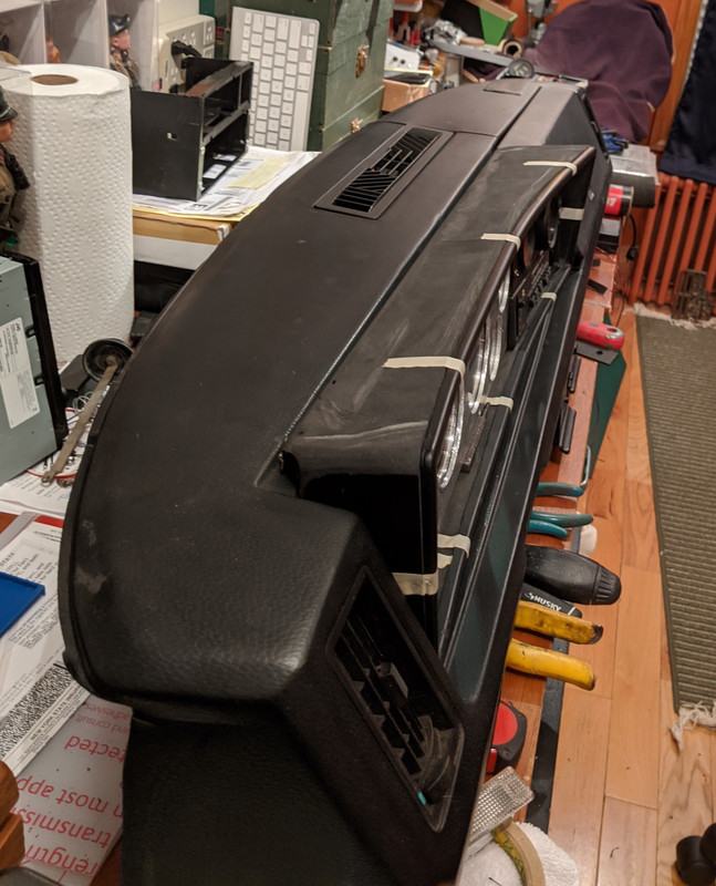
What I was using for comparison (in the setback of the cluster dept.) - the original dash layout -
-
2
-
-
Looking good so far Matt!
Better to go low amp & allow the metal to fuse instead of a large bead w/SS. The V-Bands are the toughest (for me) - getting a good angle & flowing the SS Vband into the pipe. The trick is to always start on the heavier gauge piece - which is sometimes easier said then done... This is one of mine - not a perfect weld by any means, but OK. I keep the clamp on it to reduce warping the flange from the heat. The main thing with SS is to STOP if the metal gets too hot - I'm bad at that as I'm not a patient person by nature
Curious why you didn't opt for some Mandrel bend sections - makes life much easier, except for really tight areas like the DP/hotside bend.
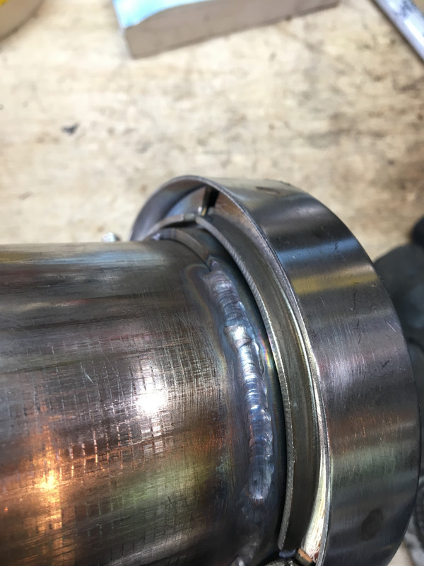
Some blobby welds visible here.
-
1
-
-
Nice work, Anthony!
For the transaxle, I just drain the unit, then refill with the 2 quarts via the detent plug on the shift gate. Saves having to remove the side mount - and on the P1's the fill plug really isn't accessible without the special tool anyway...
I know we had this conversation - it's always good to salvage the factory heat shields - MUCH cheaper than buying material that has the correct specification !
-
Nice!!! It is so much fun running a T5 motor to 8,5- 9K rpm - nothing beats the sound it makes, and with the AWD it just goes as you have found
-
 1
1
-
-
19 hours ago, Simply Volvo said:
I trimmed my bump stops today. It has a solid 1" now. I might raise up the rear a tiny more. I also soften up my dampening a ton. Now I am 8 clicks from softest. The car rides normal again. It was horrible with maxed dampening.
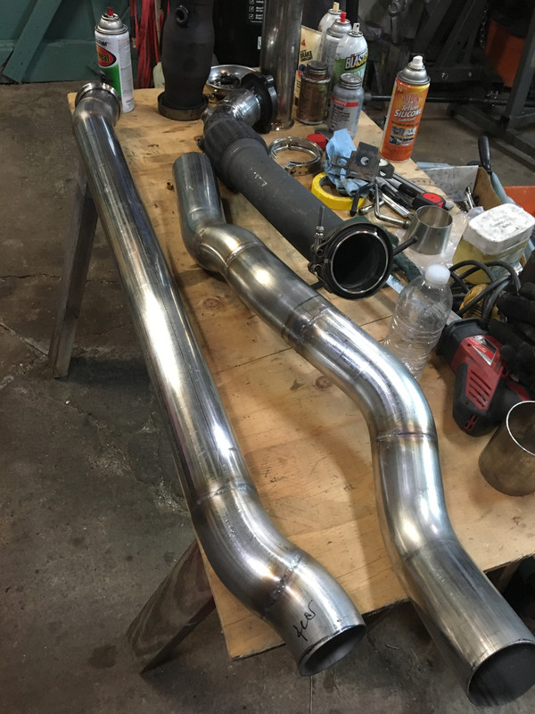
I need to start putting together a stainless exhaust system. The open 3.5" down pipe sucks and you can't hear yourself think. Definitely going to use a Borla XR-1 again and probably add a resonator too like a vibrant bottle style.
Might have a TIG welder coming in the mail soon so this will be a good first TIG project.
Wouldn't hurt to go a tad higher for now. you can always lower it progressively if the hookup issue is resolved.
I had dual Magnaflow mufflers and a Magnaflow resonator, it was still very loud and the drone was still bad. Is the Borla a quieter muffler?
I used a Stainless Works Turbo muffler on my K24 swap, much quieter than Magnaflow - also added a S40T resonator
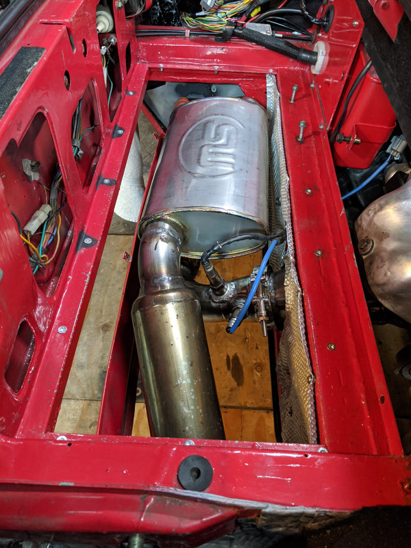
Exhaust is a good way to practice TIG. Use all SS tubing, is much easier to weld, keep the amps low, & you barely need filler rod
-
1
-
-
I think you should also raise the rear so you have at least an inch or more before bump stop - it may have some rake when not loaded, but once you launch it won't stay that way for long
-
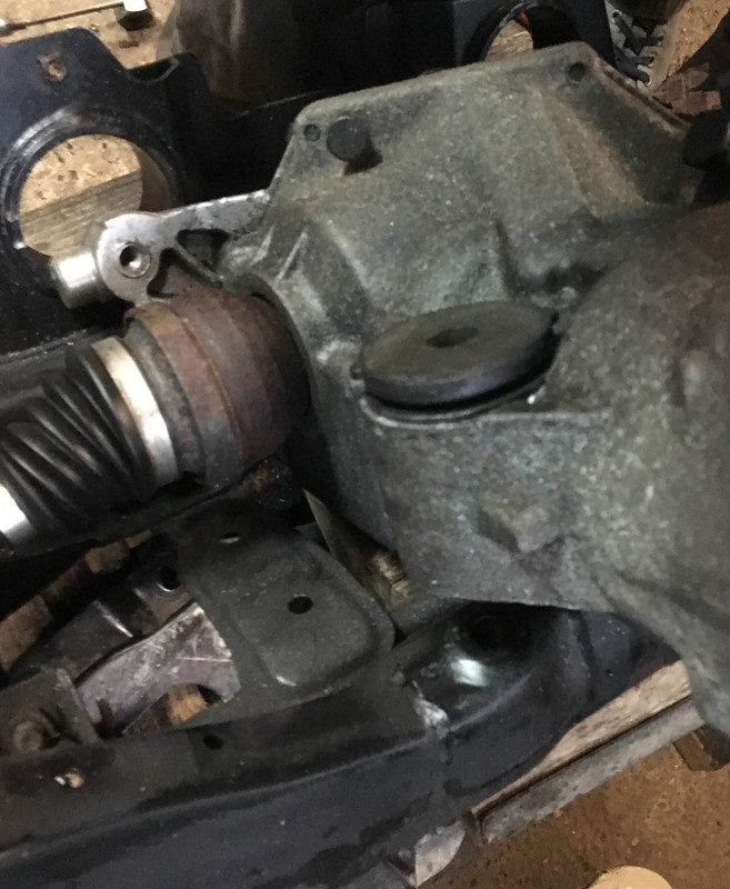
1 hour ago, apeacock said:
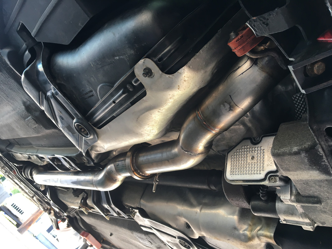
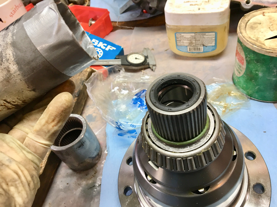
That inner seal is changed! Isn't that more of a dust one anyways at this side? I think against the transmission deep in there is the more imperative one. I believe so yes, he said to check it and come back. Need to give it another drive around now that it's cleaned up. Doesn't that left side look like it isn't touching?
its cut for the t3 on the turbo. compared to the R manifold on there now this is more free flowing a should bring back the burble
")
Yes, you're correct - the small inner seal in the BG that the axle passes though is only a dust seal - if fluid is coming out, then it's leaking from the trans case & flowing inside the ring gear tube....
Maybe this one got damaged the the axle was reinstalled - not really likely though that's the only way transaxle oil could come along & out the BG inner seal
-
Dang - they should have replaced the seal when they removed the crown wheel to do the ring - will they stand behind the work?
-
I have a minty plate from a CA '00 R - I saved it, never got around to installing it on mine
- drilling the '98 works just fine though
I would expect you'll see higher diff temps once you are loading it in AWD...
-
59 minutes ago, Simply Volvo said:
Hey H,
Yeah I could modify the diameter of my adapter to work for your axle. Just need the OD of the CV where the metal flange crimps onto and location of any recesses where the grub screws could bite into (such as channel where the metal crimps onto).
My plastic version seems to be holding up fairly well so far.
More FWD testing. OEM propshaft is on order (9463300). This a 2000 V70R propshaft with the largest carrier of em all. Should be arriving today! Also need to do a one over on all the bolts and get my new tires mounted.
Thanks, Matt. I'll get back to you when I get the axle out with accurate pics/dimensions.
Did you locate the proper center carrier plate for the '00 center shaft?
-
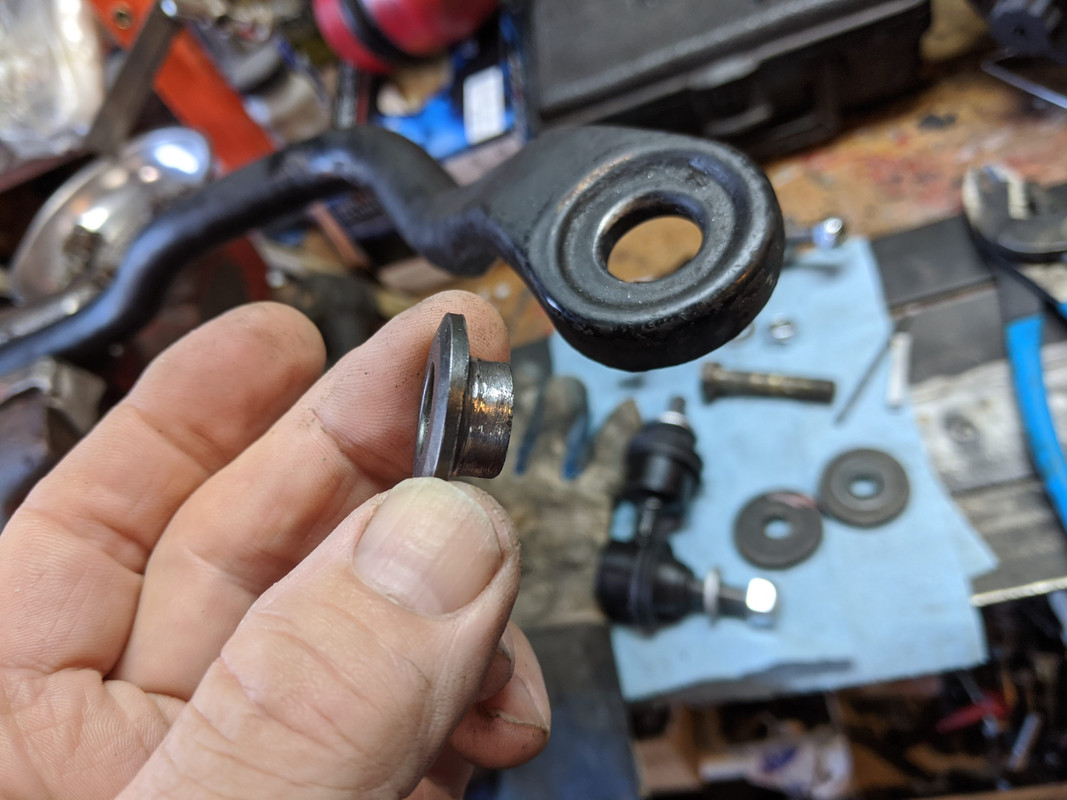
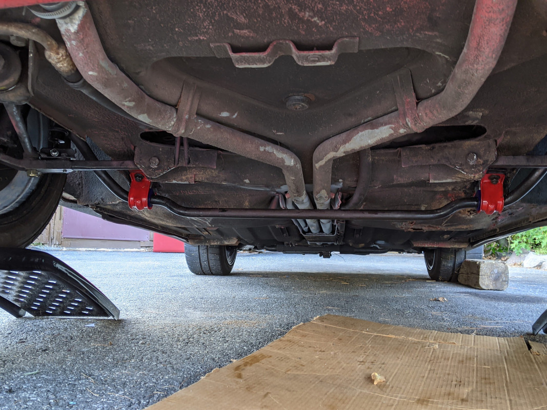
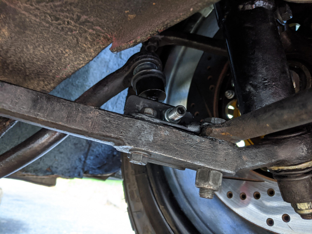
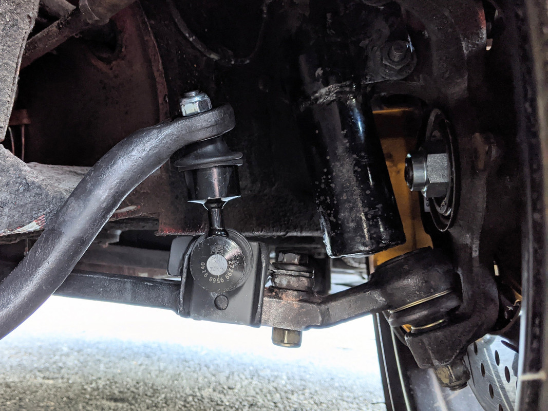
Front suspension woes - car handles like crap. Reworked the sway bar mounts and end links
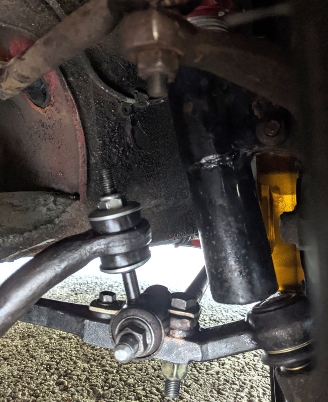
new control arms and bushings

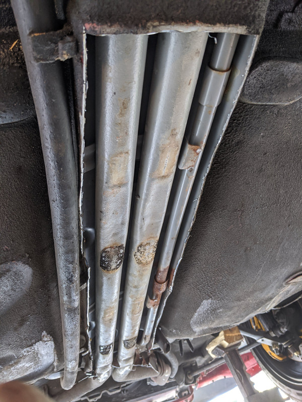
cut off the water pipe tunnel cover to inspect level of damage to pipes
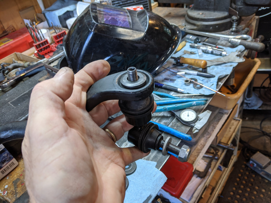
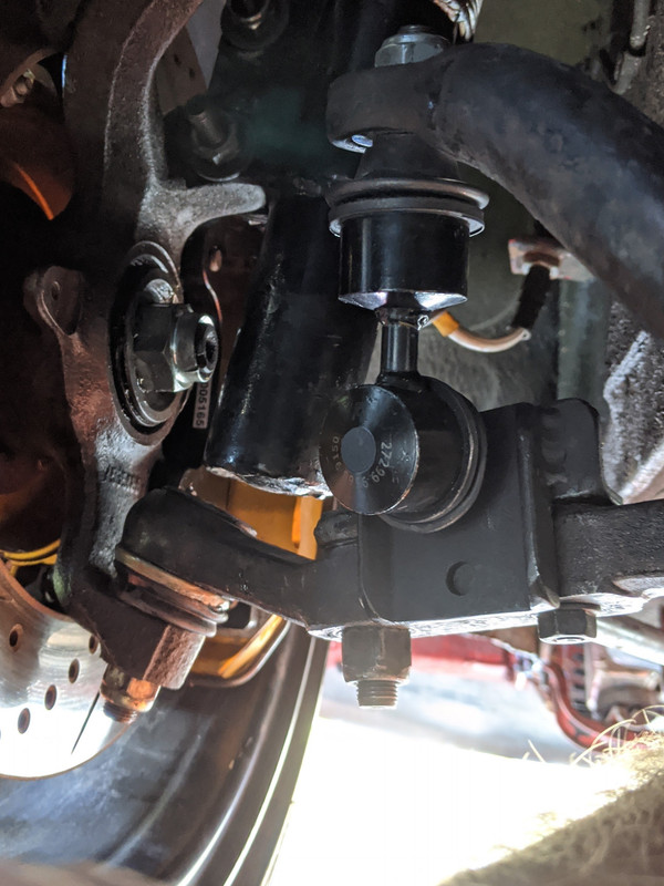
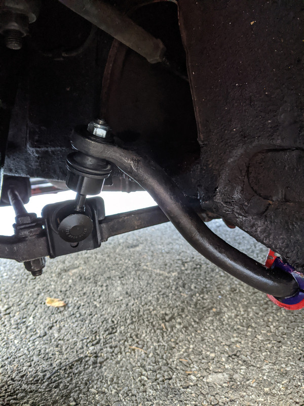
made new adaptor plates to fit C30 rear sway bare endlinks to the front - much higher degree of misalignment without binding than the old V70 AWD rear end links used previously


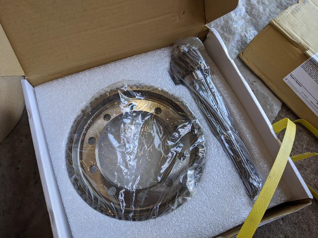
MFactory 4.00:1 R&P will go in when I drop the drivetrain to do the HG
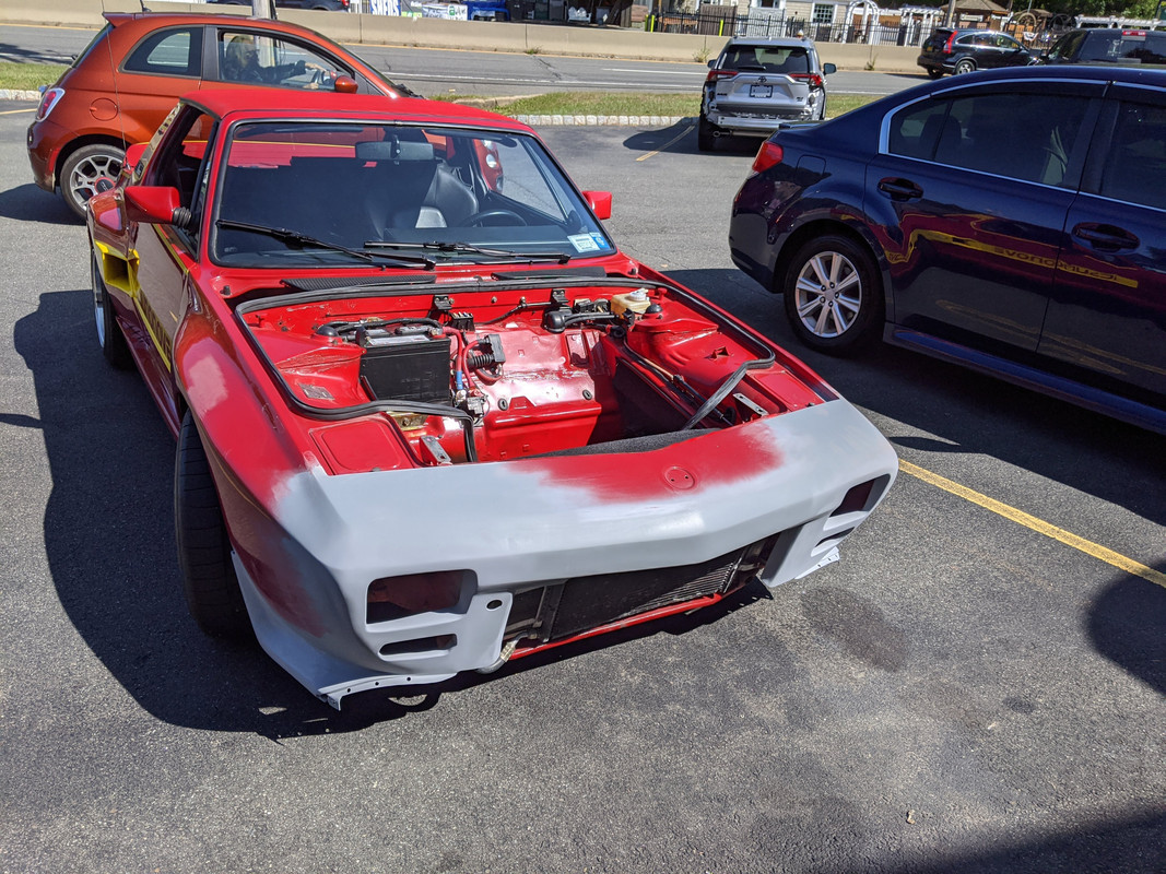
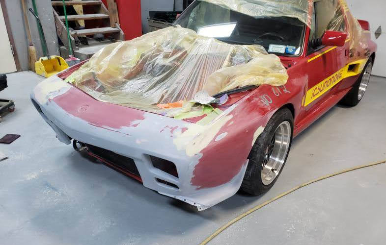
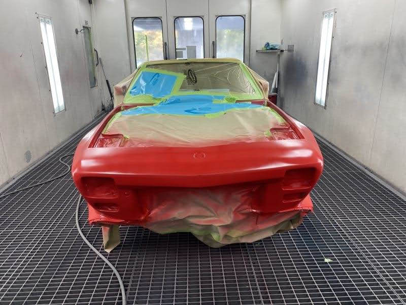
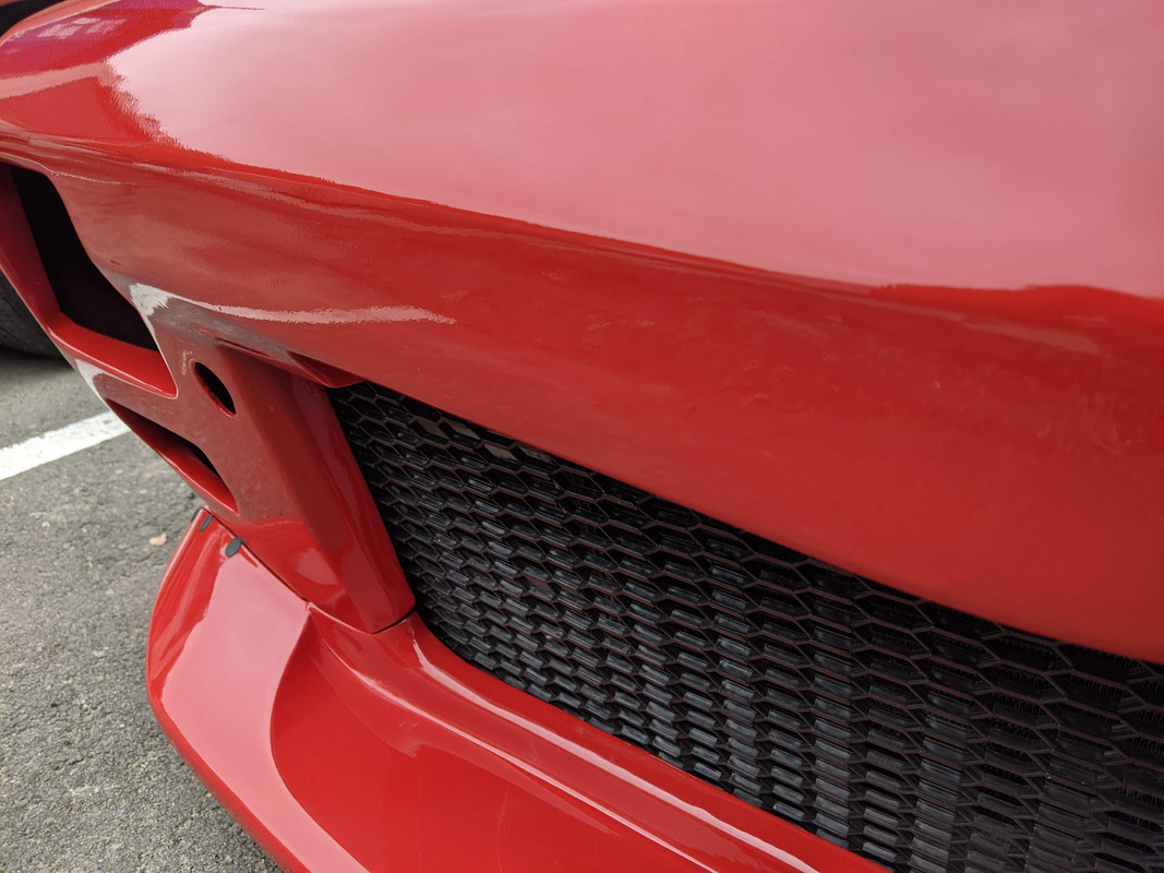
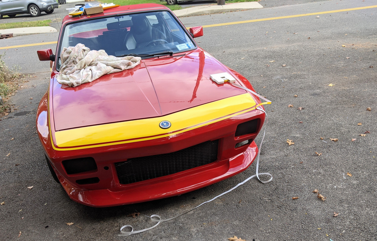
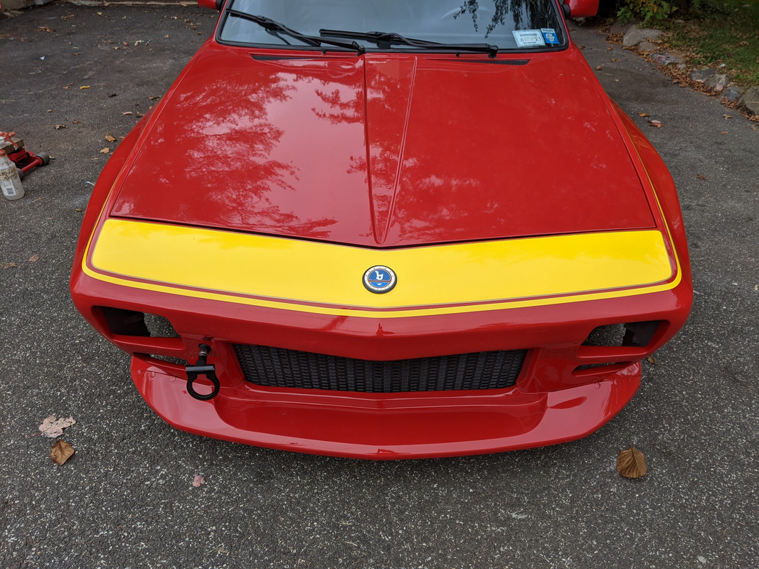
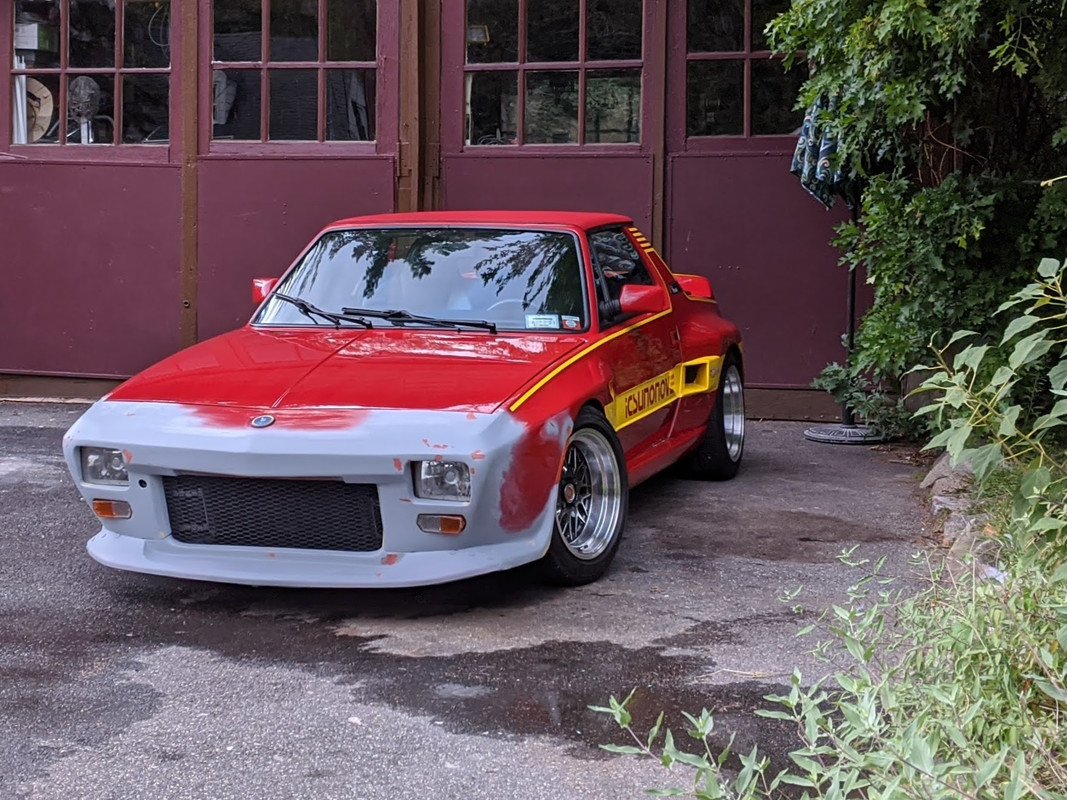
Finally got the car back from the bodyshop - pouring rain, but it's gonna be like this for days & I just want it home
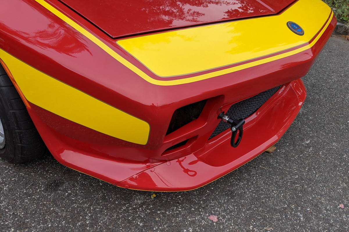
Happy with the nose, the lines where I had to merge the planes came out OK


They did have to redo some of my work on top

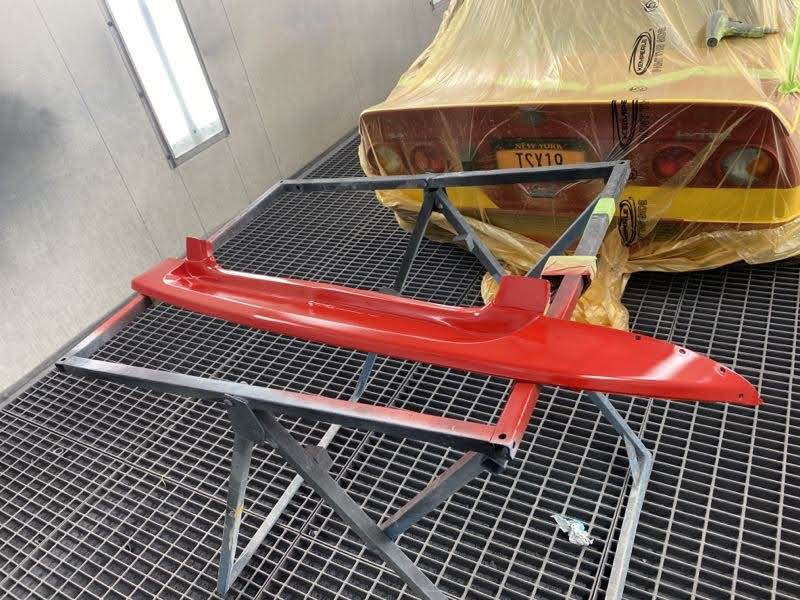
spoiler (modified S40 rear bumper cap)...
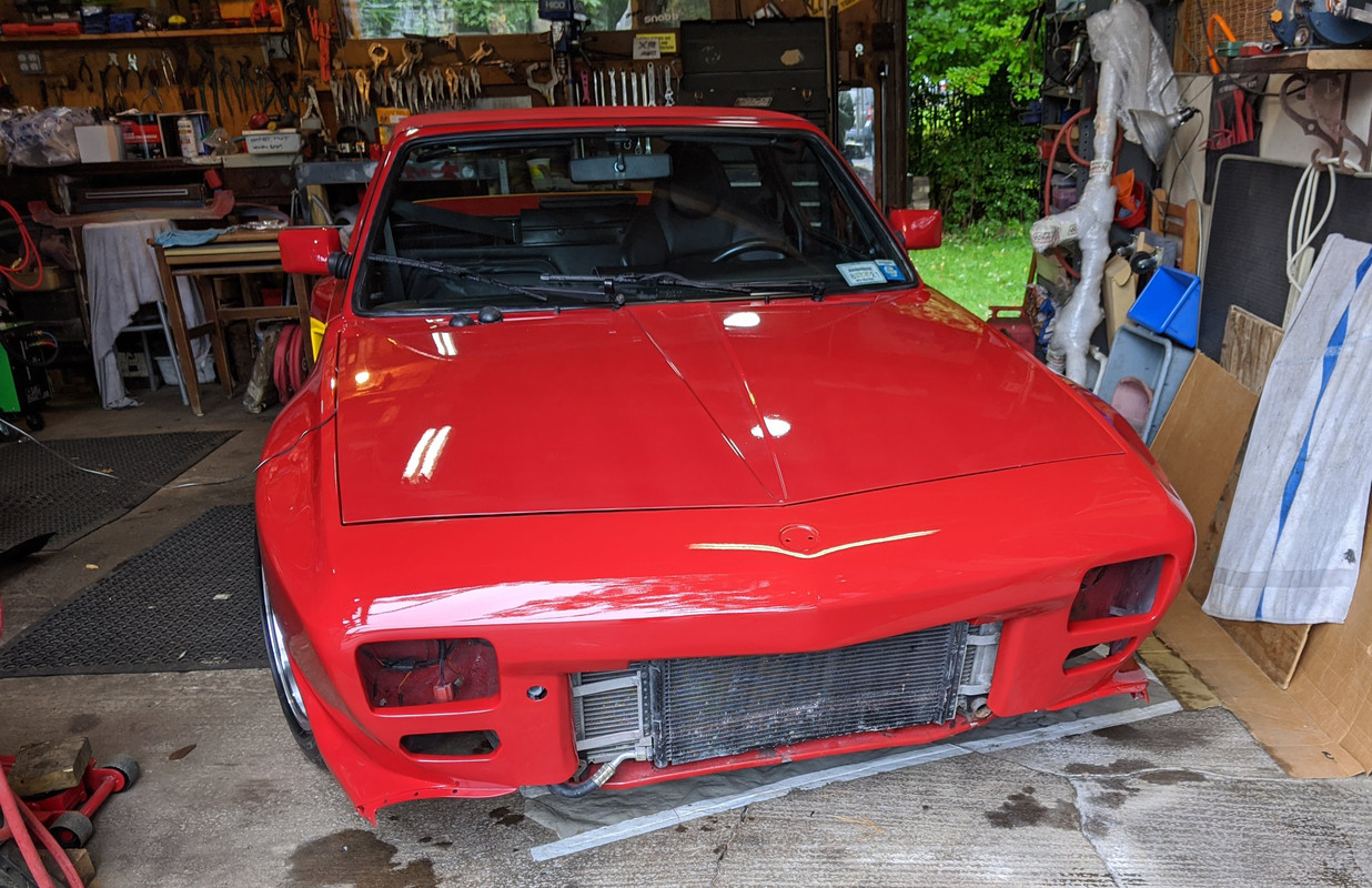

Started putting the nose back together, now that the suspension /steering work is resolved.

Got the 760 sway bar back in with the C30 end links, and SuperPro bushings (SPF1025-23K)
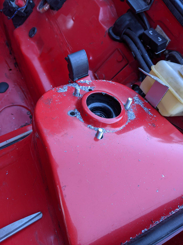
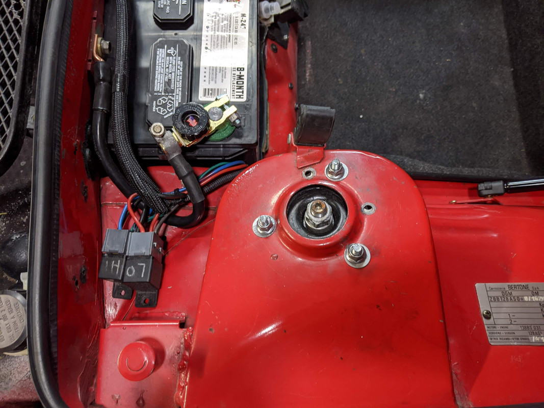
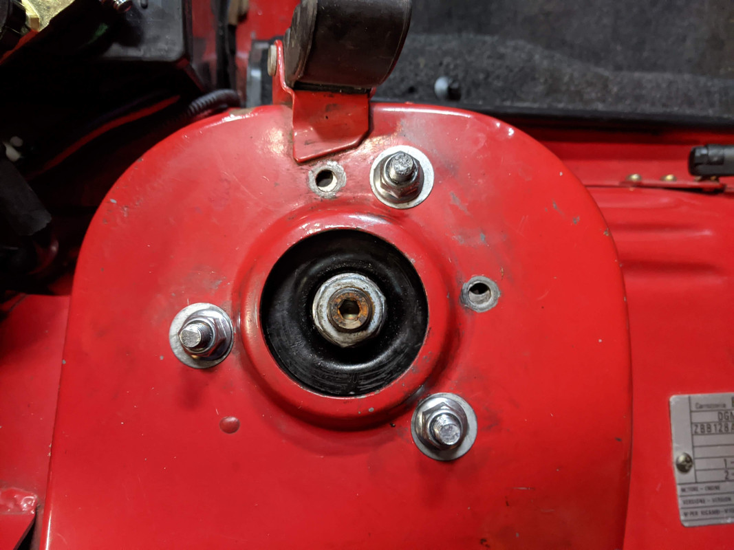
Drilled the strut towers for the Ford mounts
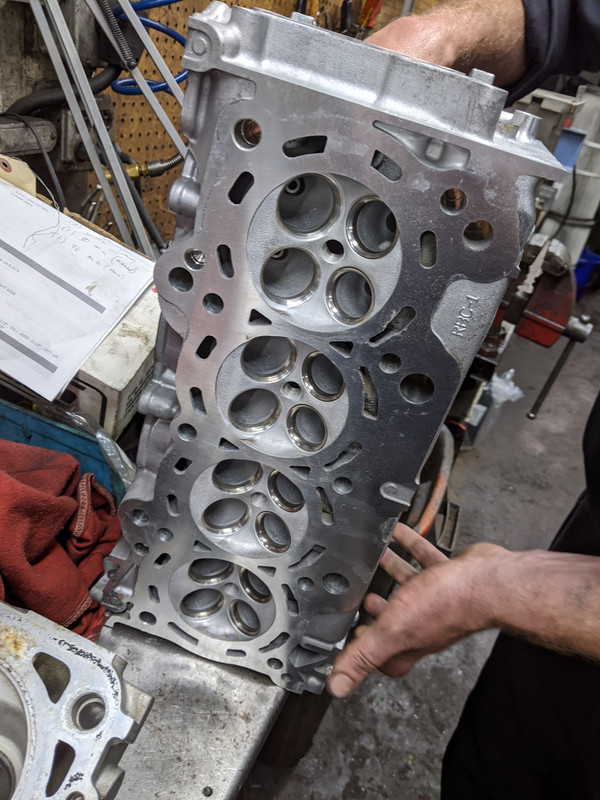
Got a K20Z3 (RBC-1) head - better flow than the RBB I have now. It is all nicely cleaned, decked & valve seats recut. Keeping the TSX cams & RBC gear limited to 40º. I'll swap it out when I drop the drivetrain to deal with the currently leaking HG, and install the 4:00 R&P.
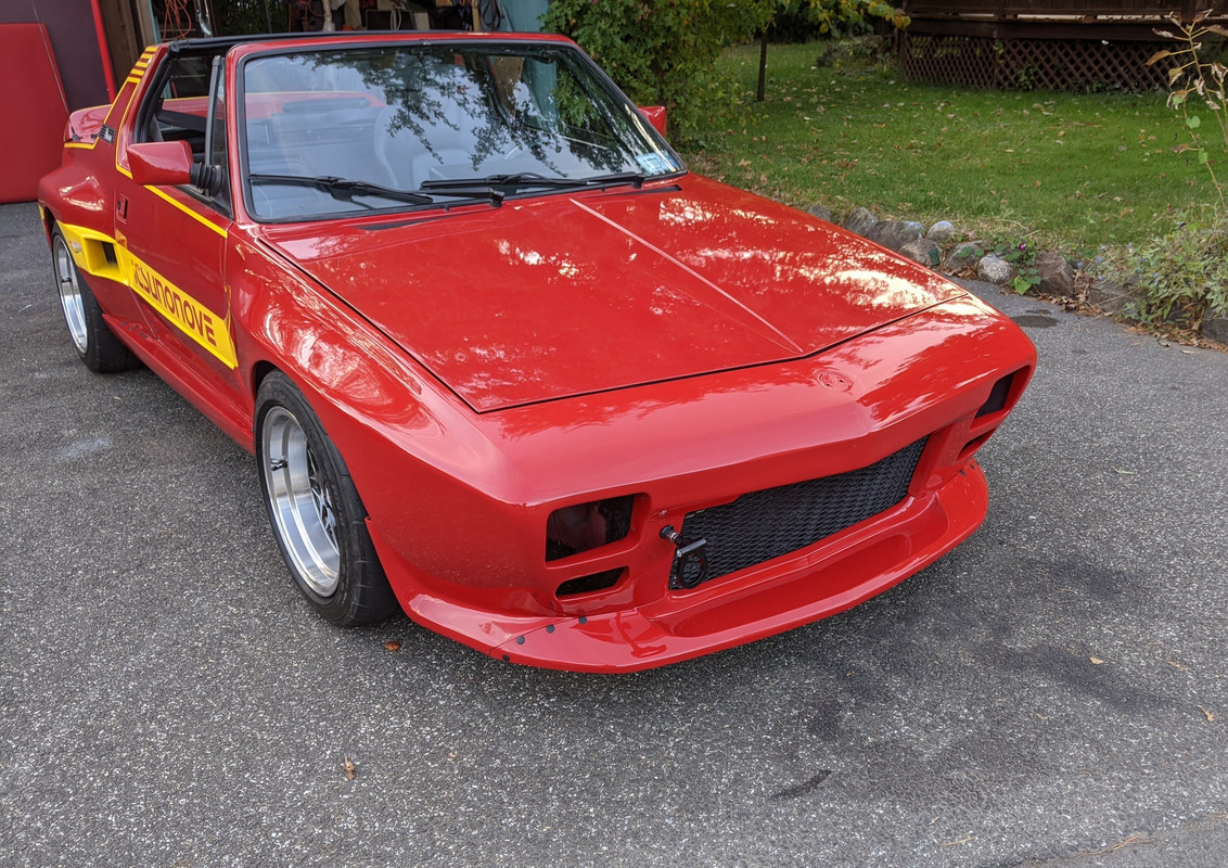
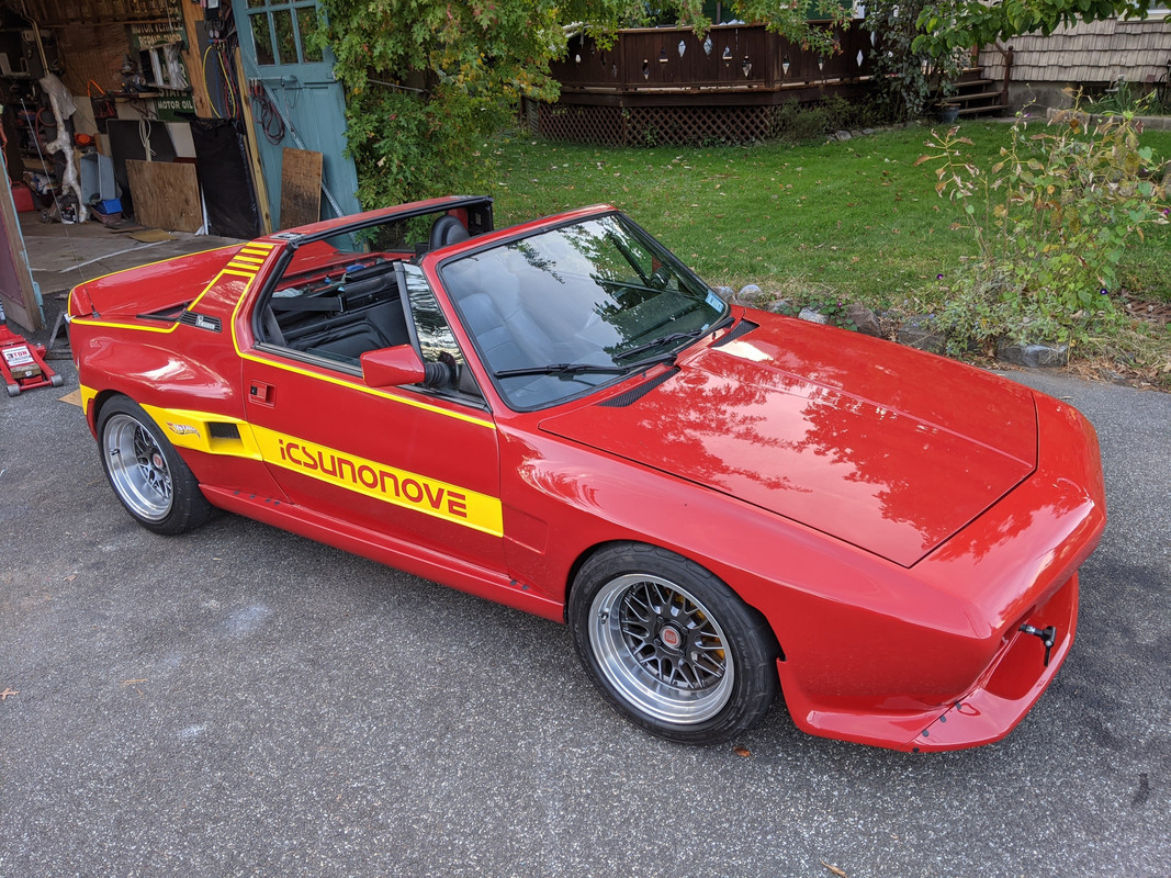
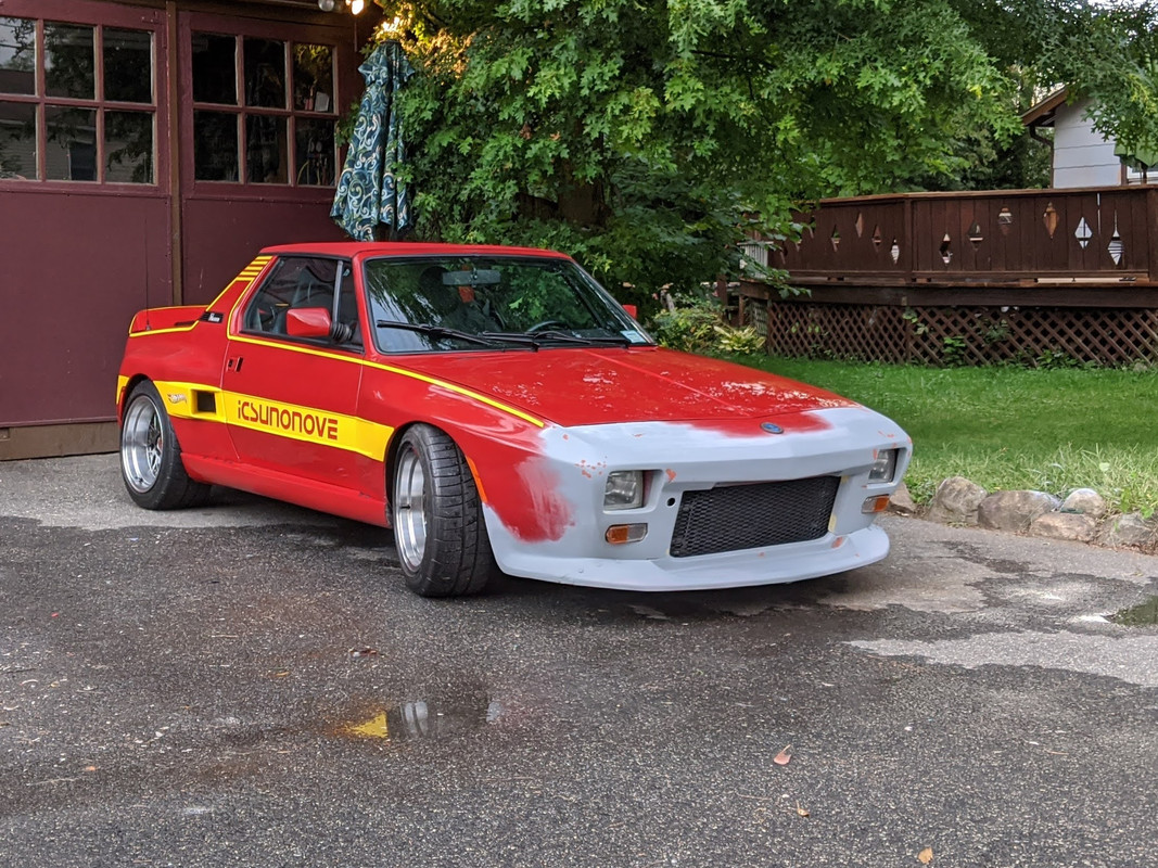
Car went back to the bodyshop this week to fix a few small things that just weren't right. All good now.

Worked on the tape stripes and decals whilst the temps are still in the 60's - I cut the decals from 3M 1080 film - easier to deal with than old school vinyl for sure
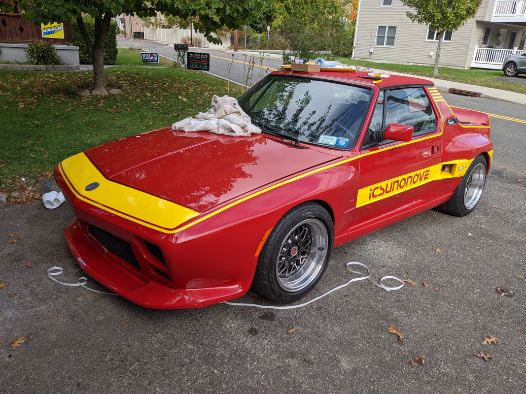
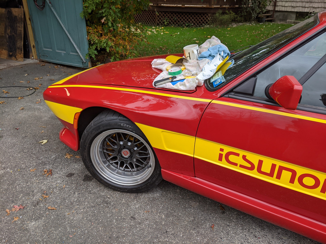
S40 rear bumper cover worked great for the spoiler
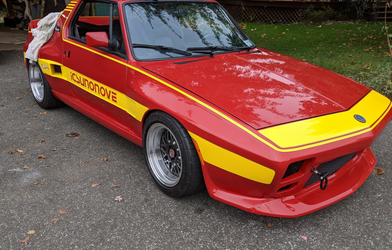
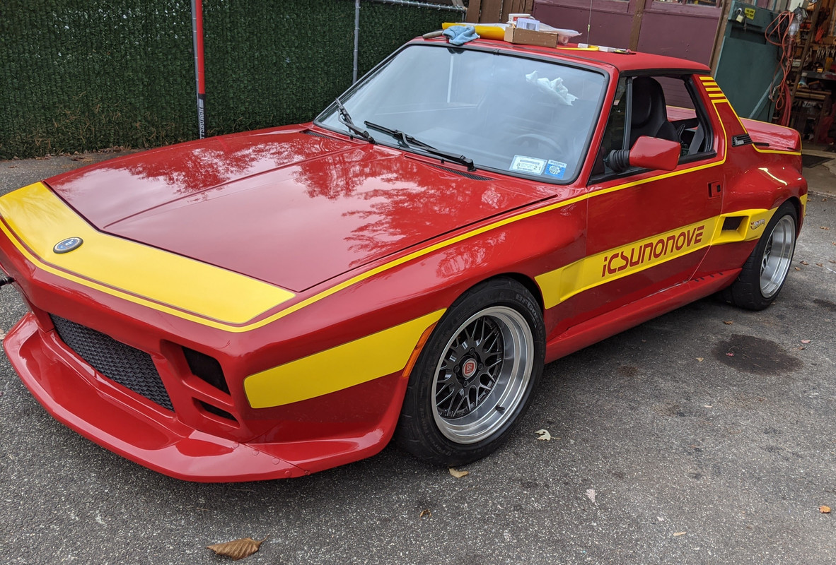
Used a 3mm gold strip to even out the (hand) cut edge

-
4
-
-
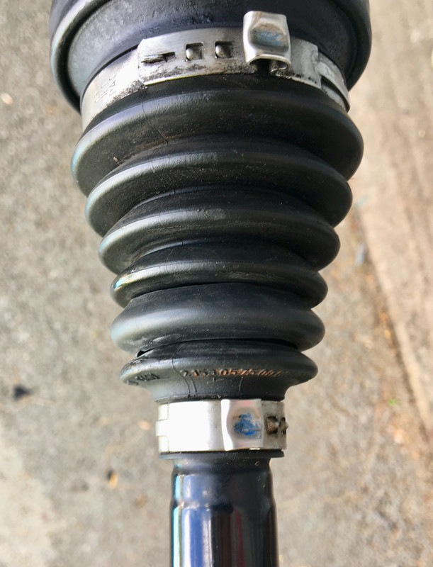
Nice work on the axle boot/adaptor flange! I think "chamfer' was the word you were searching for
Those adapter flanges would be great for P1 AWD rear axles, as the boots are also not available due to the crimp on metal flange design. As some point I will be swapping on my rear diff for the one I built with the Quaife LSD - If I dismantle the axle & get measurements for you, would you be able to 3D print a boot flange for that application?
I put a section of heat shrink over the nick in the boot - it's held up for a year, but I don't expect it to last indefinitely .
-
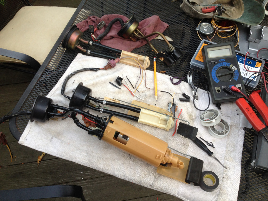
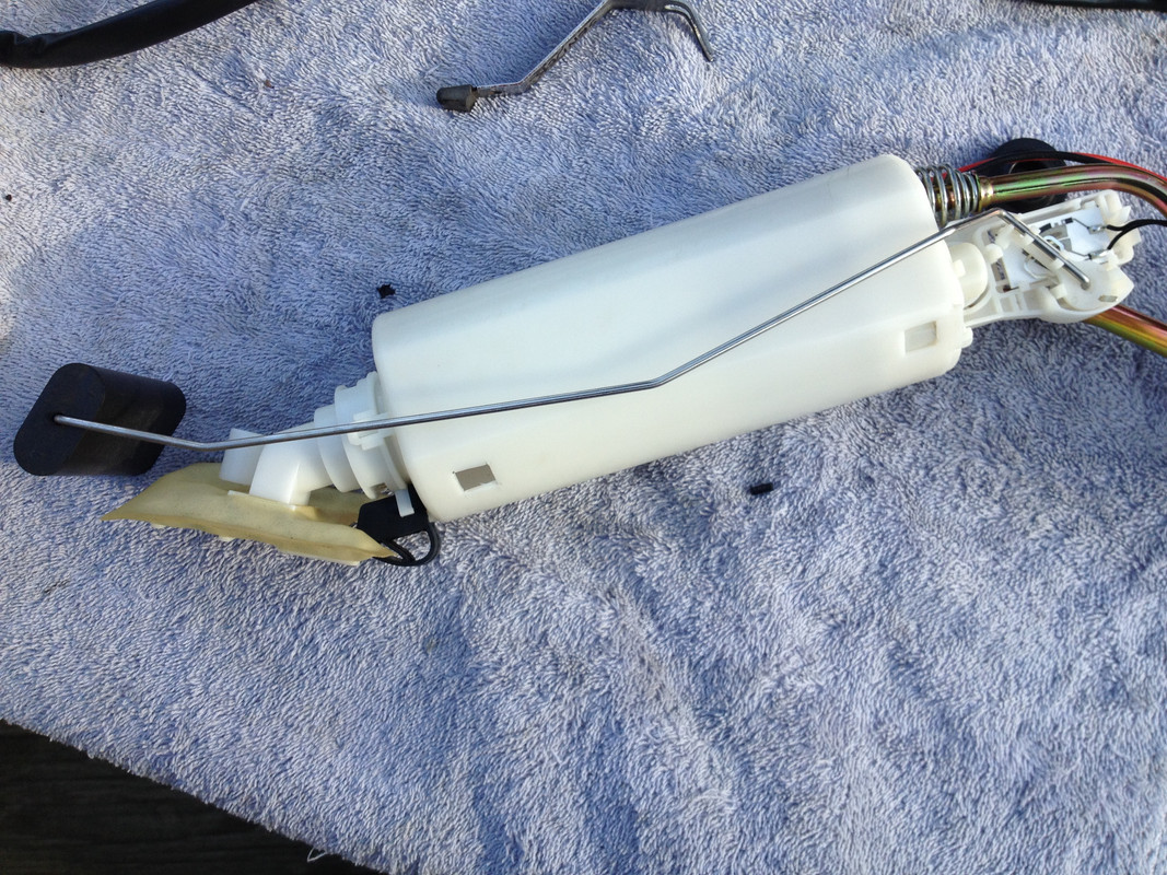
Matt - did you also increase the ID of the rigid & plastic lines inside the senders? I had done that, along with cutting a chunk out of the main sender housing to allow more rapid drawback into the tank.
Don't solder any harness connections moving forward - crimp all new terminals.
I hope that IC is not as low as it appears!
Definitely issues arise when running lowered suspension w/AWD. On my C30, over heavy highway bumps the ear on the CV Oetiker clamp hit the fuel tank filler hose - fortunately didn't cut through the hose in my case. My dampers were also set too soft, and I had to raise the spring seat 1"
Good deduction on the boot OD & damper settings.
Did you buy the later AWD front subframe tie brackets (the triangular ones)? They are more substantial than other model & earlier AWD version.
9480184
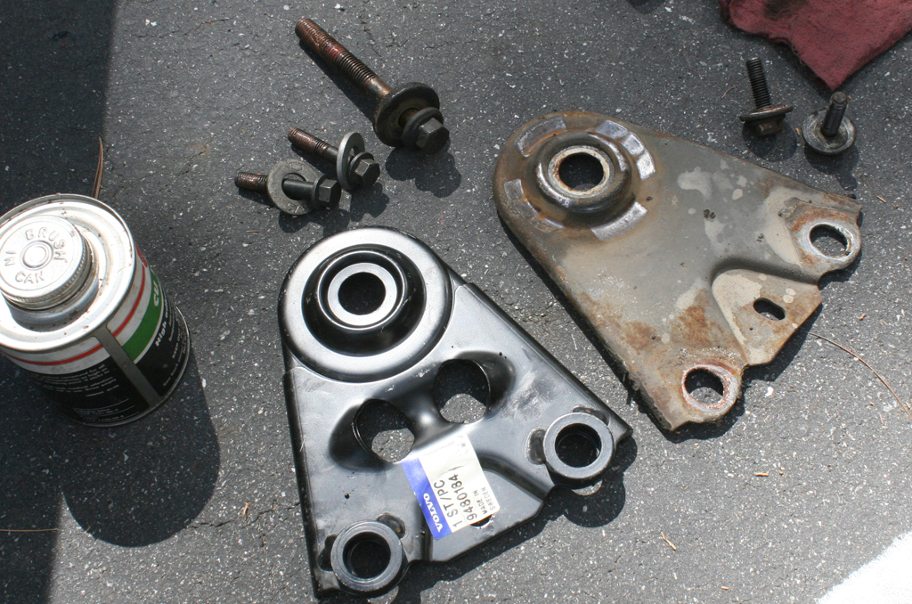
I'd look for a lower profile elbow for the AWD sump - that just looks ripe for snagging & ripping off if you go over any road debris.
-
1
-
-
Much cleanup work.
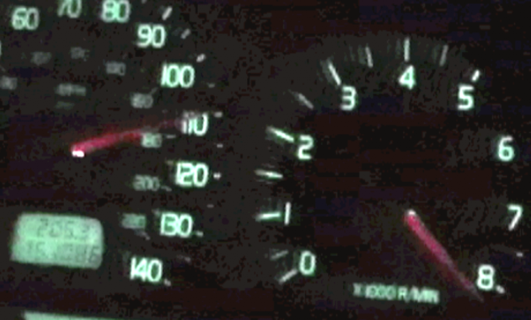
Nice mileage pic!
I also enjoy the Milwaukee M12 equipment - I got one of those stubby impacts a couple years back - really glad I did!
-
Congrats! Must feel good to have got beyond the first run
That coolant sensor (blue tip) is supposed to have a crush washer - did you add one? Also the oil pump & sender looks really close to the PS rack - I would think under hard launch you may get contact from the torque movement. Did you use a rigid mount under the crank? I had to wire my Volvo mount - back with 500AWHP it just ripped them apart otherwise.
Make sure you never use that shockproof HD in the transaxle - it will absolutely fuck up your shifts
-
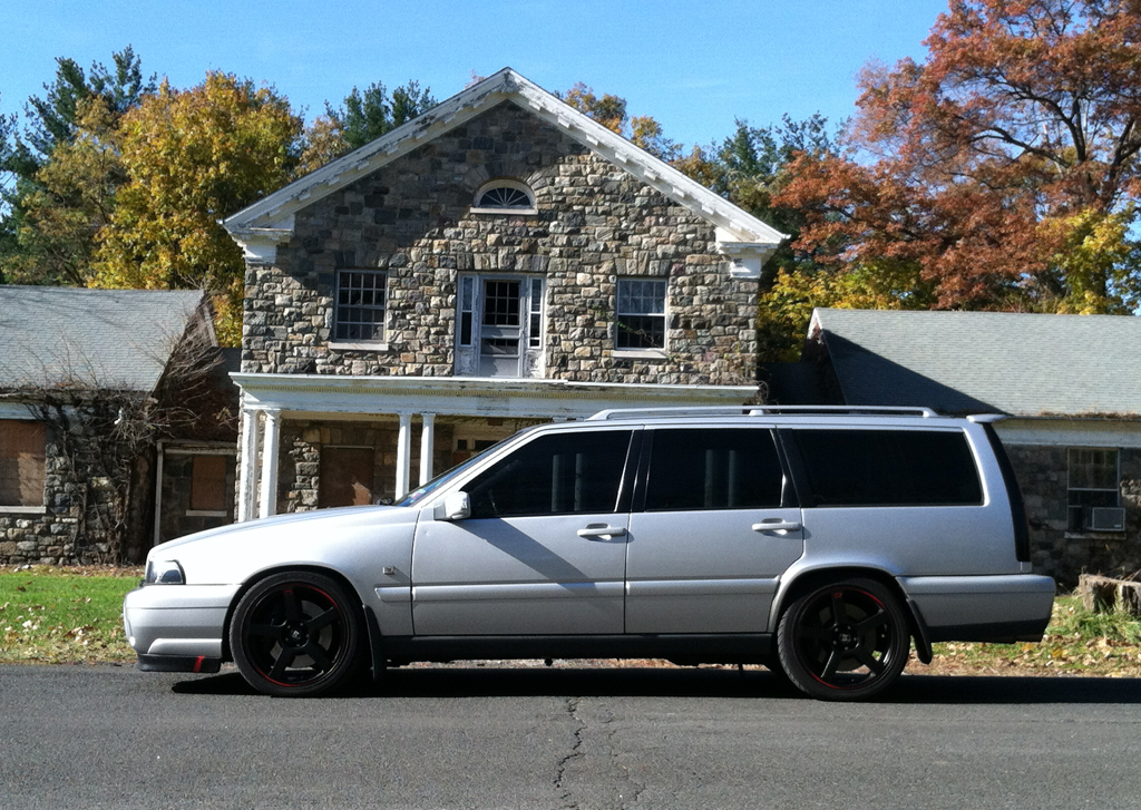
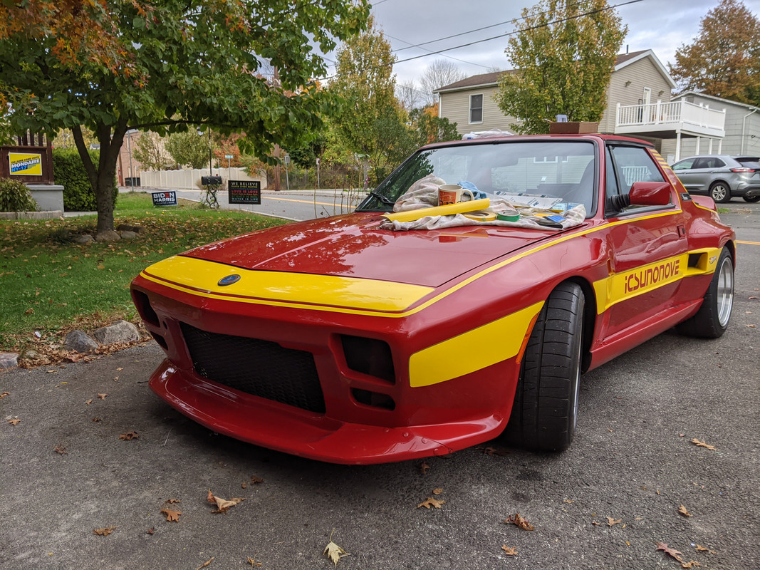
Got it off the jack stands yesterday, gave it a quick wash - it looks pretty good overall. I want to drive it for a couple weeks before I pull the drivetrain & finish the undercarriage repairs.

-
3
-


1998 V70 Xc From The Beginning... to the End
in Show Room
Posted
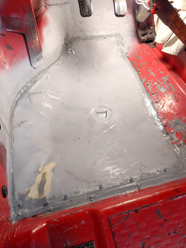
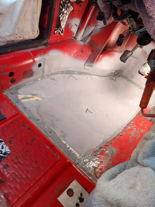
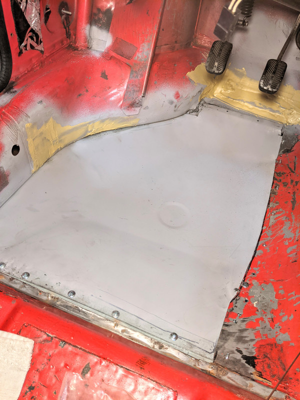
Moving along with the floor... sanded the epoxy seams, ground back the rivets, primed & ready to caulk
caulked - & final primer inside & out
Seam is reasonably concealed on this side. I think once the (3M) Rocker Schutz & Undercoat are applied it will be invisible
had time to get first layer of top coat on the inside
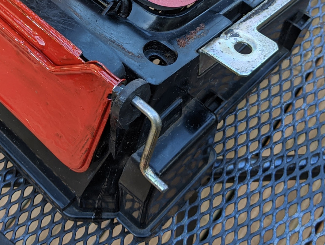
also made a housing for the power window relay mod - I used 900 series relay sockets -
based on this type retainer