

lookforjoe
-
Posts
13,471 -
Joined
-
Last visited
-
Days Won
92
Content Type
Profiles
Forums
Gallery
Blogs
Downloads
Events
Store
Bug Tracker
Posts posted by lookforjoe
-
-
Good questionVery impressive work as always. I almost hate to ask, but is there anything left to mod or now is it time to enjoy the fruits of your labor?

Next I have to tune for 28psi range. Running well at 25 on the new dwell table with GM coil packs, so far.
Then, I need to do the battery relocate so I can build a new aluminum airbox for the much larger air filter I needed to install - before the warm weather returns.
Also have a windage / Teflon crank scraper kit to go in, to reduce parasitic losses under high load conditions.
While that's going on, I need to wrap up my lh2.2 / EZK117 install in my 87 X1/9 (stroked 1600cc with euro big valve head, etc...), and switch out the Volvo/Denso alternator for a AC delco unit to go with my serpentine belt conversion on that

-
 1
1
-
-
Problems with the GM coils breakup/blowout is resolved. Many thanks again to Piet for all his time spent working on the Dwell Tables for me
No knock at any load, no breakup.
EDIT: Only up to 21psi. Refer to Tuner Rejoice Thread, Aug 2015. TMM9 found a problem with the dwell voltage lookup axis. More work to be done s of 8/10/15.


-
3
-
-
My friend tested those GM coils in his 680hp gasoline 9-3 Saab (Vigge/Olde) and those were not good. Then hi swapped VAG coils and no problems. VAG coils are equal on power as T5 Volvo Stock Coils.
Check your dwell time (ignition coil charging time) ???
There are different versions. Did they use the LS2 variety like mine with the heat sinks? They are used on 1000HP setups, I think they are fine
 - Dwell tables are a work in progress
Have enough voltage on the coils?
Not a power supply or ground issue. Most likely Dwell table adjustments. I've read of similar conditions on the Supra forum.
This is a trace from the log at the point of breakup under full load. The table was created based on the requirement of 3.5ms @ 14v .


-
Been running the GM coil packs for a couple of days.
Needs some work on the software side. Fortunately I have some help with that - math is just not my thing.


-
2
-
-
Odd, weren't they used ones?
They were - but all the others were new & that didn't make any difference. Drove about 200 miles home today, and as long as I gently accelerated, I could get up to about 12psi under increasing load before breakup. Trying to rapidly load it created an immediate (negative) response.
I have to figure precisely which pack(s) have failed. Unfortunately, I don't recall taking notes when the previous ones failed as to which cylinders were the problem. 3 & 5 (edit- it was 1&5) are what spring to mind, but I'm unsure. I will have to swap out one at a time until I get it figured out.
In the mean time, I can hopefully get the adaptor harness made for the GM coil packs. I'm going to add a connector into the harness near the rear cam seals, so I can switch between setups

M

. I would think there is a good chance that the problem is in the harness, if it's consistently the same packs that fail, no? I did check the connectors for any evidence of overheating, both in the harness & the coil packs without finding anything, though.
EDIT 12/15. - found I had one previously unused coil - so I swapped it out starting with no. 5 & worked back towards no.1. Breakup went away once I reached no.2. Now I need to test my other 10 to see which of those are bad....
-
Hopefully (and probabely) you will never have to find out
Unfortunately the problem (breakup under load) is back. Happened Friday afternoon. I'm out of town until tomorrow, so just driving it under gentle throttle until I can figure out which pack(s) have failed. Time to get cracking on the GM coil pack wiring - it's been miserable cold/wet weather which is why I haven't done the wiring yet...
Thanks Maarten!
-
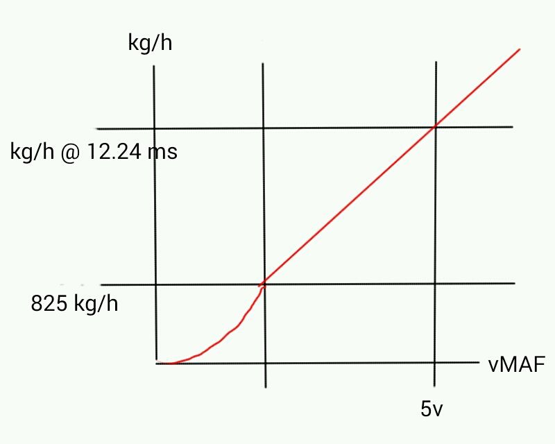
Why not fool the ECU by decreasing the slope of the MAF curve after let's say the stock max value of 825 kg/h. A linear line from the 825kg/hr value to the point where both the maf voltage maxes on the x-axis, and the kg/h number maxes the load (@12.24) on the y axis would suffice.
This last kg/h number depends on the injector constant. (You can find it by looking at the kg/h number in the logs at the point where load maxes out).
This means that you can use the stock maps up to the load generated by the stock max 825 kg/h, and you only need to tune for the part that comes after that.
The load numbers will not reflect the same load anymore, but who cares about that anyway...
After all load isn't something real, it's just an invention to make it possible to mix the right amount of fuel with the incoming oxygen under varying circumstances. Load can be rescaled itself as well, therefore the max value of 12.24 can be related to a much higher amount of incoming air.
Piet & Venderbroeck
I'll have to read this over a few times to absorb it - math related computations do no compute readily
Run today - quick 3rd - 4th. AFR's too rich now, so I'll back off the WOT settings .01
60-120 6.67sec, even though I didn't go WOT until almost 70 & shifted 3-4 - feels really good

You're tuning at wide open throttle on what I would assume is the same road. Sure your fueling is fine now, but what happens when you actually go out and drive the car on a different road or under different conditions?
I use a road that has level, downhill & a long uphill so that the conditions vary but in a consistent way
-
I max out load at around 3800 RPM on my setup, then fueling becomes hard to keep steady. I set up a VE map switcher that switches the VE map based on airflow values when the load is maxed. I'm still working on it, but I can share a version with you once I feel confident in it.
By the way, I'm looking for your details about your DW300 in tank install, but can't find it because your sig has DW300 in it. Can you point me to the correct page?
Interesting. I'm not maxing out the MAF, so if higher load values are not available, your table switching allows a rescale of the load table?
At this point I'm hoping it's just tweaking of the upper load cells to refine the AFR. I know my fueling is not an issue. The peak boost does vary with changes in ambient temp/ air moisture content, it seems.
The most frustrating thing is the built in 7650 rev limit. At the very least I'd like to be able to log actual RPM again, even if the EMS can't be altered to acknowledge it in its calculations.
That link Andy posted outlines the DW300 install - pump polarity is reversed, so be sure you use their pigtail. You can always PM me if there are item specifics.
-
Another pull to check the upper load cells. Still lean. Hitting max load under 30% throttle.

tweaked the involved load & WOT cells, see how that goes

2124 kg/hr @ 7620 rpm

-
Another pull yesterday - this time peak boost was 26.3 psi - it was a tad lean... I moved the 100% load cell values back to the pre-dyno settings after this.


Max flow 2100kg/hr @ 7650rpm.
-
Nice! About time you moved on from that old rad. Only so much luck you can have
-
Nice Work! Always good to see the carnage ;)
-
1
-
 1
1
-
-
Very nice, a little bit of knock, but just a bit.
What is up with the knock % column?
Knock Enrichment as Piet surmised.
How did the car feel during this pull?
Feels Great!
After removing less than a degree up top, I did another quick pull, this time in 4th instead of starting in 3rd. AFR's are about 1 point leaner! Peak recorded boost 25.7psi.
Forgot to include air flow column - (4th gear) 4.84v @ 6840rpm = 2007.88 Kg/hr

Also, when in 5th part throttle, too lean & got some knock. Have to tweak those full load cells.

-
Did a 3rd-4th pull today to 8K. TunerPro only goes to 7650rpm. First hard pull since switching the onboard COP. About 25psi boost, 10 sec 60-138mph. Have some work to do on the timing map. AFR's look good.

-
Do I see AN fitting ? I am so proud of You !!!
INDEED - AN fittings all over the place -
-
Is the heat shield really required? The bunch of bananas look too cool H. Don't hide them!
I can remove them in the winter/spring months. Don't think I want to run without in the summer - pretty sure it will heat soak, even with my hood vents...
-
Nice! That's better than my choicesAll up to you.
Changed the title for the time being until you make up your mind.
Got up around 1 degree Celcuis today - so I spent a little time test fitting the coils and plates before I make the wiring harness

#3 & #4 need a little adjustment in spacing,
Too close to IC pipe - has to be lowered for coil wire clearance

Touch too close to the oil cap - it will scratch it if fully locked

otherwise it's looking good to me.
-
1
-
-
What title do you want?
any one of these:
Hussein's 1998 V70 XR : Under Construction
Hussein's 1998 V70 XR : Ongoing Changes
Hussein's 1998 V70 XR : Work In Progress
Hussein's 1998 V70 XR : What's Next?
-
Newer Oil Pan W/Oil Cooler on a weekly basis..

Can you open the Thread so I can edit the title?
-
Does this have any connection to the topic title anymore ? I feel like we're losing info here..
Yes, it does - since I'm always revising the Tune and all the Hardware thats connected

I'll have to contact a moderator & see if I can revise the title regarding the oil cooler part...
This is interesting stuff, I'am interested in using this coils also.
Whether their dwell wil be limited to about 140 degr or not, I consider them as an upgrade anyhow.
B.t.w. I calculated the table out of the given values for LS2 coils, so it it's not suited for LS1 coils.
Yes - it's the LS2 (D585) that I have, with the heat sinks.
-
This is interesting. Thanks for taking the time to work out the tables & for considering the potential software/coding side issues.
I pm'd TMM9 - see if he has any input - I'm pretty sure he was/is planning on using LS1 coils, along with Simply Volvo.
The wagon is running very nicely with the onboard COP & stock Bosch Coils, so this may all be unnecessary, but it's always nice to have options (and more stuff to fabricate/work out) :D
-
I think it's using a shift register to handle the different coils. This would mean that it can handle only one coil at a time, and no overlap would be possible. It could be made to work with software alterations, but this would not be easy. It would have to set the next coil in line after the current charging one to high at a calculated time before its turn in the shift register. Essentially, it would need to handle the 'begin charging' point of 2 coils at the same time. The firing is unaltered of course.
By It, do you mean MegaSquirt as opposed to coil operation M4.4? Is this related to the discussion of 'overdwell'? Wouldn't a 8 cylinder that the coils are designed for have even less time? Or that just means the EMS is setup differently?
"Spark duration only comes into play when there's not enough time to allow the full spark and discharge time periods. This mostly applies to a single coil on V8s or more.
i.e. at 6000rpm each engine cycle (720 deg) takes 20ms. Eight cylinders fire per cycle, so time available = 20 / 8 = 2.5ms. The code maintains a balance between time to charge and time to fire the coil.
Now, in a true coil-on-plug install you have the full 20ms to charge and fire, so the spark duration value does not come into play.
Even with say 4ms dwell and 1ms spark duration, you would need to be turning 24000rpm before the available time equals the required time.
James"
-
I'am not quite sure if the software (the bin) can handle dwell times over 140 degr since it is originally written for a standard coil which has to fire 5 times in two revolutions of the crank which means 5 times per 720 degr.
Leaving 720/5=144 degr for charging and spark.
Could be it can, but i'am just not sure of it
Maybe TMM9 knows?
Thanks for figuring out the table Piet. I messaged TMM9 to see if he has any thoughts or knowledge of this.
-
Looks tidy, did those coils come with dwell times?
No.
Found this on a LS1 forum. If this replaces the main Dwell Map & (upper bank) map contents, what about the Dwell Map -Time table? EDIT - These ARE the dwell time tables - it's the degree maps that are in question


Discussion of over- Dwell settings

Alternate Map


and this is from MS manual/coils. Not sure exactly where the low noise ground should terminate ("B"), since we only have three wires. Perhaps tied to another signal ground at the ECU connector? Not sure if I assume the capacitors (similar) are already integrated into the ECU or whether it would be prudent to add them.


Hussein's 1998 V70 Xr : The Force Awakens
in Performance Modifications
Posted
Yes, thanks to Piet - he is the one working on the software.
The table probably can be refined, since his changes are all educated guesses based on other systems that people have used them in (thanks Justus & Nathan for your tables). He needs a coil to determine it's precise capabilities at different voltages, so I'll send him one for further research.