

lookforjoe
-
Posts
13,471 -
Joined
-
Last visited
-
Days Won
92
Content Type
Profiles
Forums
Gallery
Blogs
Downloads
Events
Store
Bug Tracker
Posts posted by lookforjoe
-
-
A few updates.
Fuel system upgrades were finished a couple of months ago.
AN-08 Fuel inlet to rail

Left sender access
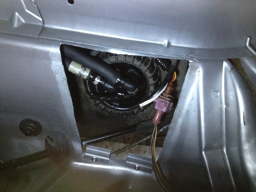
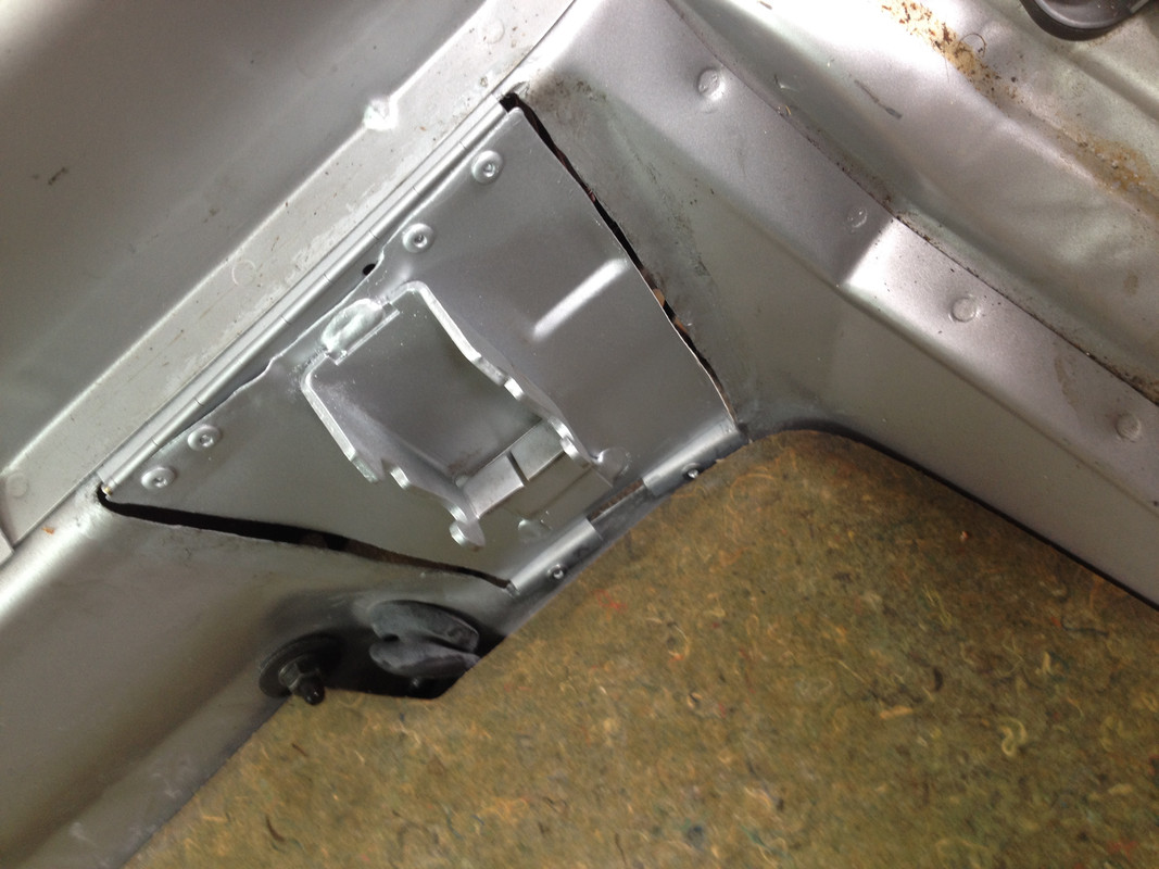
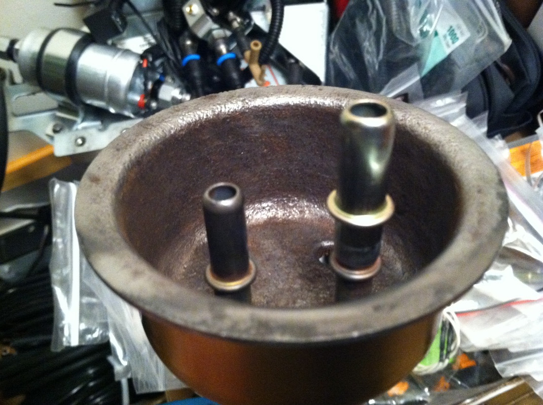
All lines uprated to 12mm. All fittings on senders now 3/8", with 3/8" tubing replacing stock 5/16"

SS LGSpeed Header to replace the mild steel version that rotted out at the collector
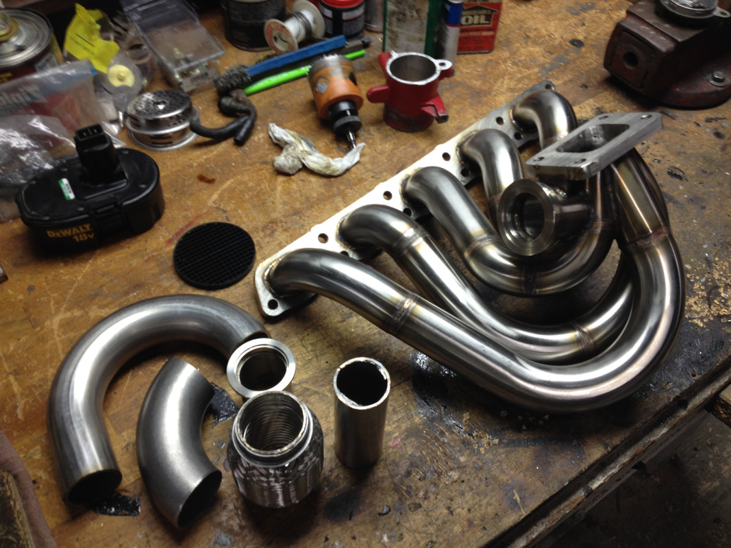
Revised SS DP to go with

SS intermediate section with Magnaflow 14419 resonator

I will redo the tail section in mandrel bend SS when I replace the Magnaflow 14834's with the longer body (quieter) Magnaflows. No I have the TIG, I can do it all myself.
Now running onboard COP instead of TTCOP - I added the connector for TTCOP inside the ECU, so I can switch if needed.

A friend gave me this light table, which made soldering the resistors much easier

Once I have the confirmed all my coil pack issues are behind me, I will get back to the dyno
CEIKA rear BBK finally installed. 330mm, 6 piston calipers.


GM D585 Coil packs going in next


-
They always say knowledge is power - in this case it is more literal, since the more data we collect, the better we can tune :)
-
Bloody Hell. What specs?
Engine pulls very nicely - seems cleaner/ crisper with the onboard COP. I see less soot on heavy throttle, so perhaps part of the issue was difference in dwell timing, Big hole in collector not withstanding...
-
Lookin proper.
When's the redo on the dyno?
Probably not until I have determined whether the COP failure is a thing of the past, it was very unnerving when it broke up on the dyno.
-
Color shift after a few WOT pulls

Finally running onboard COP, thank avinitlarge for catching my mistake on the 47k ohm resistors, and to Piet for helping with the conversion of my earlier bin, and to Aaron for his work on developing the COP functionality


Curious to see if this affects my burning coil packs, and whether COP related codes will be set - never had a single CEL for cylinder blowout due to coil failure with TTCOP, as many times as it happened.
-
 1
1
-
-
Those exhaust header look amazing especially with the golden/bronze. Will you wrap them or power coat for heat retention?
No. I would have done that prior to installation. I previously made a heat shield that I will put back once I've made absolutely sure there's no problems with the new line routings back there...
-
Checking if your O2 is operational is extremely easy using tunerpro.
Compare you nominal air consumption at idle to your old logs, see if it matches and if it doesn't, you know you have an air leak.
That would work if it would have idled...
I swapped out the O2 for a Walker I had, until the Bosch arrives. Reset the ECU, and all is well.
I'm still killing Bosch coil packs -(with TTCOP). I did a hard pull up a local steep hill during my preliminary check out, and it started breaking up. Swapped out the coil packs for another 5 used ones, and problem fixed. I'll have to swap them back one at a time to find the actual dead one(s).
Now its all OK, Ill move ahead with the GM coils install.
Pretty Headers


-
Is your turbo ball bearing or journal bearing version?
Mine is BB.
Car is all back together & running, but now it doesn't want to idle - AFR's go lean & it stalls out on decel/idle rpm. Have to check over a few things. I'm going to swap out the O2 - I didn't have a new Bosch one on hand - perhaps it was damaged from the heating required to remove it from the old DP. Engine idled fine prior to the work, so I think it's either that or a fitting/hose that I didn't recheck.
-
What is the size of your turbo oil feed line restrictor?
The restrictor is fitted by Precision, and removing it voids their warranty, so I can't answer the question as to what the ID is.
The restrictor has 1/8" NPT threads, and they specify using a AN04 - 1/8NPT adaptor to then fit what line you may need.
-
Bought a TIG from Eastwood a couple of years ago. Primarily so I could do aluminum work. SS is easy by comparison - however the speed shop guy said I still used too much current - the weld should be more a pretty rainbow hue rather than the gray I have. That's OK, Practice makes ProgressWhat are you using for a welder, looking good.
Of course, the return of the yellow pad is welcome.
Kingsborne modified wire set came today
Same price as the standard dimension wire set for an 850, in 8mm w/LS2 boots with 3.5" open wire length. Judging that off Trent's pic.
Oil feed line also arrived with a new 4-an - 1/8" NPT straight adaptor to go into the Precision supplied restrictor seat. 27" length line, listing was for Mazda installation to get the banjo end. edit: wrong size banjo - reused the -4AN to M14(?) that I already had from prior installation. Feed hose was also approx 24". , so a little extra length to deal with routing away from the headers and hotside.

-
Waiting for oil feed line to come in.
I decided to work on a couple of details to make header removal a little less painful. The main problem (as far as the flange to head fitment goes) is that there is no clearance to fit the upper nuts and washers on 3,4,5 due to the runner offset. The only way is to pull the header away from the head to gain clearance. That is a problem as the turbo flange has almost no firewall clearance even when bolted tight to the head
[

After dicking around with the old header on a spare head, it seems the easiest solution is to shorten those three studs by about 4 threads

Now the flange lock nut can be placed with the header up against the head.


I ground down the sides of a good 13mm wrench, and chamfered the top / bottom so that it would squeeze in place over the nut


Still a pain, but now more tolerable since 18ftlbs can easily be achieved with a normal length wrench such as this.
This is the intermediate pipe I reworked in SS. Close fit all around, but no contact with tunnel
-
2
-
-
Nice. I wish I had more uneventful put togethers

Nice!
Always good to have friends to help push things along.
Totally blanking here but CC?
Cruise Control.
-
Yeah - I can also use it for repairing my Joes - I used to be able to repaint the eyes, eyebrows, etc without any optical assistanceI always used Optivisors in my days as a bench technician doing this sort of work; That lighted magnification table looks awfully handy.

The oils used for the features tend to rub off in travel


-
4
-
-
Got the correct resistors soldered for on board COP - I had bought 47k ohm instead of 47 ohm
I was given this magnifying table a couple of weeks ago - don't know how I soldered the other chips only wearing my reading glasses, this made life so much easier
-
Those sensors look the same as the 0-100psi range I have used for fuel and oil pressure - I have only had problems with the terminals coming out the housing over time.
For CC pressure/vac I used a Volvo NA MAP, since the table is readily available.
-
Too bad you couldn't move or angle the wg dump so it's not dumping directly after the turbine. Without extending the WG out further, it looks almost unavoidable.
Fab work looks good though
Were you able to get a brace in there?Yes - that's why on the old header I added a longer extension for the WG - however, that was one of the points that cracked, so the stress must increase the further off you hang it. This one also has a brace to the flange, even though its short. I did consider trying to divert it out & around, but there's not enough free space. It would have also meant a DP that cannot be removed without dropping the subframe like my old one.
I'm building an adjustable tension support that will push up under the hotside using valve springs gauged to support the specific weight of the turbo - my speed shop guy has done this for other setups, in my case I have the angle drive conveniently provided a shelf.

-
Finished up the DP, swapped over the O2 sensors (had to repair the threads after pulling them from the old DP),


fabricated a new intermediate pipe with the Magnaflow Resonator. Got everything buttoned up, started it up & found the oil pressure feed line is leaking at the elbow where it attaches to the turbo. Have to order a new flex line. PITA is that the turbo has to be dropped to access the fitting.
-
Very impressive H, I would be bleeding everywhere. How heavy is that exhaust manifold?
Trent, I forgot to weigh the SS header before I installed it. The PTE 6262bb weighs 19.5lbs. I'll weigh the older header, the SS version felt a little lighter perhaps, but that that different.
-
Spent about 2 hours trying to make a flex coupling for the WG dump without success, so I went with a rigid coupler

Just have to add the two O2 bungs.

Header is back in, & turbo is in place.
-
Sure it looks cool, but no yellow pad drawing?
Not this time, I just eyeball the pipes & cut based on what feels right
-
Very impressive H, I would be bleeding everywhere. How heavy is that exhaust manifold?
I'll weigh it. Don't know off hand.
-
Are you going to dump the wastegate to atmosphere or plumb it back into the exhaust again?
No screamer pipe. The last couple of pics covered my WG dump options
-
Removed the SS braiding layer from the coupler - with that, the coupler fits between the firewall & swaybar.

clearance going down


Removed the header. turbo & DP so I can now fabricate the coupler for the WG dump

no way to fit a flex coupler unless I remove the braiding & cut it down to just a few inches

May just go with a rigid junction

Have to weld the O2 bungs in place also, and redo the straight pipe back to the resonator in SS pipe also.
-
2
-
-
 :blink:
 I do wonder if having the manifold ceramic coated would have preserved it?
I would assume so - my X1/9 headers are ceramic coated, and even though they fucked up around the flange and the collector, it's still in one piece after more years than this one, and that sits around unused much more.


Hussein's 1998 V70 Xr : The Force Awakens
in Performance Modifications
Posted
Cleaned up fitment of coil pack plates & test fit coil packs/wires in a spare head
