

lookforjoe
-
Posts
13,471 -
Joined
-
Last visited
-
Days Won
92
Content Type
Profiles
Forums
Gallery
Blogs
Downloads
Events
Store
Bug Tracker
Posts posted by lookforjoe
-
-
Test fit the manifold & turbo.

With production variations/tolerances the new header pushes the coldside firmly into the heat shield.

DP is cut from SS mandrel bend


Firewall / swaybar clearance without 3" ID flex coupler

Have to figure out if there is any way to make a modified flex coupler between the DP & WG dump. I have a flex coupler at the base of the DP where it runs back, I think I'm gonna leave it at that. Otherwise, the coupler will be wedged between firewall & swaybar like before, and servicing / removing DP in one piece with that in place is not an option. Welding SS is like butter compared to aluminum :)
-
 3
3
-
 1
1
-
-
eeek! Good god. How many miles?
I don't remember exactly when I installed it - it was on my old engine / hybrid 20g setup, so around 40k & a few years. Not a long time, in other words.
-
Collector rust & cracks


Pretty sure they ground down a fair bit to tailor the flow on the inside, perhaps they just went too far.
Header is moving on to a new home

Got the EGT and EBP bungs welded in place

Tomorrow I need to get this all test fit so I can mock up the new DP
-
1
-
-
Butt welded
And no cracking issues? That's good - so I'll do the same with mine - SS pipe is not forgiving if you try to expand it..
I am going to make a support under the hotside - I should be able to make a tension mount that pushes up from the angle drive to fully support the weight of the turbo. That should ensure that when the header is expanding/contracting it's not dealing with all that weight hanging.
-
. Keep in mind the stainless manifold will expand/contract more than the mild version and may be even more prone to cracking. Is your turbo supported/braced? Might be something to consider adding.
Bugger. Yeah, perhaps an additional support would be a good idea. Needs to be spring steel, like the tang used on older volvo exhaust braces.
Keep forgetting to ask - Did you butt-weld your SS DP? Or are the joints lapped?
-
Took over two fucking hours to remove the fucking header. The way the runners are designed, there is little clearance for a socket. Had to chamfer grind a closed 13mm wrench to get two of them loose, then undo 1/2 a flat at a time.
Good news ( in that even though the flange nuts are absolute bollocks to access & tighten, they hadn't loosened over the past 35k) is that the only leakage was at the collector, the manifold was all good - all the sooting was blowing out the collector cracks.

Now I have to fabricate a new DP to fit the revised WG positioning - which is so close to the DP flange, I see no way to refit an expansion coupler. Pics later.
-
1
-
-
For a run like this, I would only use oxygen-free copper (OFC) as opposed to the less expensive copper-clad aluminum (CCA) due to the improved current handling capacity and resistance to corrosion (causing voltage drop, etc)
I ran mine through the factor opening on the driver's side of the firewall. This required removing the stock corrugated plastic tubing
Here's a link to the wire I used: http://www.knukonceptz.com/mobile-audio/power-wire/kolossus-fleks-kable/sp/kolossus-fleks-kable-10-red-power-ground-wire/
And it is extremely flexible, it makes routing the wire through tight areas very easy
Thanks for the tip, I have already ordered the Summit kit though. My firewall pass through is completely used up with my many data logging sensor wiring. I'm gonna have think about this.
Thank you for the linky - good read on the various linked threads.
-
I don't have any... but I could take some. It's just a JEGS battery relocation kit. Cable is through the floor, down the inside of the cabin at the doors and through the firewall. Like standard amp wire routing.
Can't find the exact kit I used... but it is either similar to or exactly this : http://www.jegs.com/i/JEGS+Performance+Products/555/10275/10002/-1
If I had to do it again... I would go to the junk yard and look for BMW stuff.
How did you pass the cable through the firewall - I'm curious how to handle that. I've ordered the 1/0 ga kit off Summit along with a distribution block & some other connectors. Pics of the mounting in the back would be nice too
Yea with all the weight you have up front with that thing I would definitely want the battery in the trunk.
If the battery is gone you could easily use that space to build a nice shroud around the fliter.
I'm going to make a large can for the filter, offset using some of the space where the battery is now
-
Time to move up to an M66 (or much newer M56) - but that would mean a new clutch disc, since the splines are different

-
Spent some time going over the system components today. What I found was that the MAF Honeycomb had dislodged & was restricting/interfering with airflow over the MAF filament. With the screen removed, the super rich condition was removed. With that resolved, I started pulling the DP off.
The DP/WG flange has been leaking


Looks like the manifold is leaking at the flange

The Header is cracked at the collector, I'll be able to explore that once I have it off the engine.
I thought the DP was leaking, but no sign of leakage. Had to chop it off at the 3" ID flex coupler - no way to remove that between the firewall & subframe/swaybar

New Drain tube


Worked a little on the GM coil mount plates. #3 needs to go either here

or here

Other four will all point this way

-
I'm running 0ga in all of my cars. But it's generic wire from flea bay.
hhmmm.... pricing it out that way, doesn't seem to be that much less, though.
What about ANL fuse blocks? Did you add one to the + cable? Close to the battery?
-
Updates for season 2015:
-Fuel pressure data logging with 0-7bar sensor
-Crankcase pressure data logging with 0-0.4bar sensor
-New turbo oil return to rear of new oil pan (over oil level) 19mm hose
-Extra oil return from catchcan to front side of oil pan (over oil level) 16mm hose
Please take pics as you go along
I redid my drain tube in 3/4" (19mm) ID SS flex tube with AN 12 fittings.

-
Sorry, didn't realise your budget only allows for new, blue boxed parts to be used..
.
Sorry, that didn't go across as intended - didn't mean that as an attack on you
Regarding the relocation, I'm mainly concerned over whether 2ga is perfectly sufficient or whether it's just wiser to use 1 ga.
-
I don't have any... but I could take some. It's just a JEGS battery relocation kit. Cable is through the floor, down the inside of the cabin at the doors and through the firewall. Like standard amp wire routing.
Can't find the exact kit I used... but it is either similar to or exactly this : http://www.jegs.com/i/JEGS+Performance+Products/555/10275/10002/-1
2 gauge is sufficient? Seems like the kits are either 2ga for around 100 or 1ga for around 160.
-
I don't have any... but I could take some. It's just a JEGS battery relocation kit. Cable is through the floor, down the inside of the cabin at the doors and through the firewall. Like standard amp wire routing.
If I had to do it again... I would go to the junk yard and look for BMW stuff.
I'll look into it. What wrong with the Jegs kit? If it's quality of connections, I'd rather build from scratch. No cutting corners with that ish. JY resources non existant here , so that's not an option. I think I'd rather run the cables under the car rather than through it, though.
Installing the correct cover panel for the changer option work as well but installing a tilt sensor would become more difficult if you ever want one.
Tilt sensor??? OEM cd changer cover??? You know we are talking about 16-17 year old car, right ? Volvo NA doesn't maintain stock of accessory items or parts for accessory kits for anywhere near that time span you do realize... ;)
-
Sorry... you're quite right... no trunk.
I put mine in the passenger corner. It fits quite nicely... no loss of the spare and really is never in the way.
Any links to pics of your install? Cable routing?
-
No trunk - cargo area

It would have to go in the center well - which would mean no spare. No a great trade off for an early AWD subject to component wear if driven any distance on a flat/ low tire. Still, I'll have to consider it an option
Too cold and set to touch the wagon today - so I worked on my coil pack mount plate/cam cover

-
I wonder if the header wrap tape caused (corrosion) issues? I've heard mixed reviews on that stuff.
I'm sure it is a contributing factor, since the header is mild steel. It is very heavy gauge however. The main cracking/rust that I can see from the top is in the collector 'crotch', which is not wrapped. I'll know the extent of the underside cracking/rot once I get it off the wagon.
you might want to try to reroute that filter to the inner fender area. Seems like you are out of room in the engine bay and that filter looks pretty crowded.
Yeah. That would require a significant redesign of the battery location, the breather can & all my hose routings and cutting a 4" hole in the inner fender ; nevermind that the Charcoal cannister occupies the available space in the forward inner fender region. Even if I were to relocate that, I'm unsure that a 7-8" can could be fit any more easily than in the bay. I'm going to start with the 8"x1' cylinder I bought, and contour it to the available space - it only needs to be round at the filter neck, from there it can be more elliptical in cross section.
-
GM coils will likely be positioned somewhere along these lines:


making an aluminum two piece cover to mount the coils & replace the existing cover.

Coil packs will be on standoffs. there will be standoffs for the two plates. there will be openings for the coil wire to pass through.
Cracked header has got to the point where to car is running like shit, so I have to deal with that ASAP.
-
What kind of oil temps are you seeing?
Don't know right now. Once I have my new sensor logging device, I will be able to add back all the channels I had with Innovate/Logworks, oil temp included.
Hope you understand what i mean.
I get the gist of it.
Thanks Aaron. I'll spend a little time with that & see if I can establish 3 reference points.
-
(115 x 8000 x (44/14.7+1)) / 3456 = 1064 This is how i calculated it because it says CFM required for a turbocharged or supercharged motor = (Pounds of Boost / 14.7) + 1
Add 1.0 to this answer.
Example: (CID x maximum RPM x #4 ) / 3456 or 1728
That pounds of boost / 14.7 + 1 means pressureratio from compressor map and pounds of boost is boost pressure.
I calculated that your engine would need with 28psi boost about 1000cfm of air and similar air filter as i have. Your current air filter is too small and its weakening your turbos performance and turbo is now in higher point on your compressor map.
Thanks for that - I didn't understand the +1. Indeed, in that case my filter is too small - I calculated 998.5 CFM as you say. I'll have to look for larger filter... again
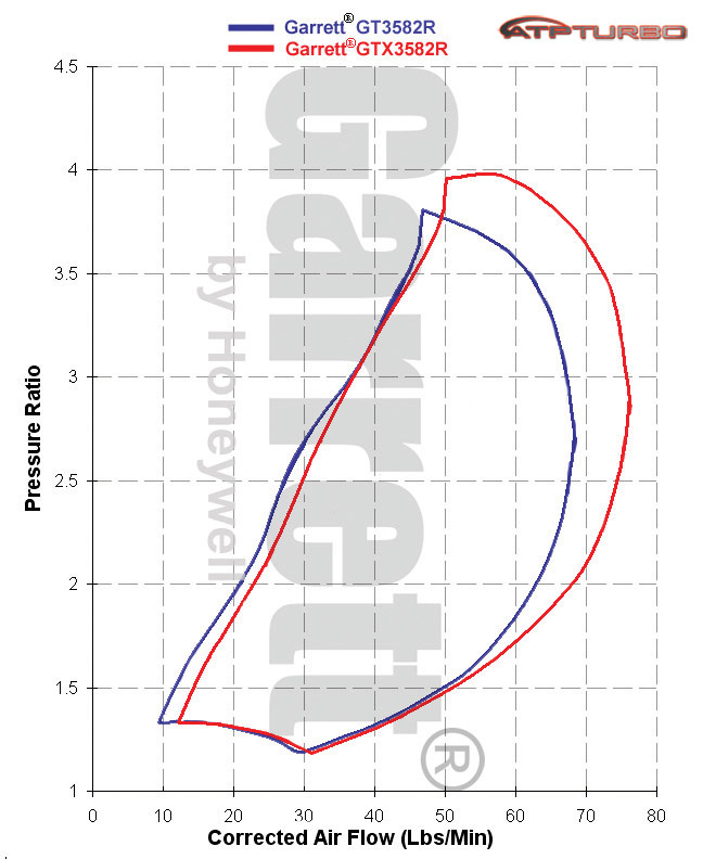
I have never seen any compressor maps for the PTE turbos, and wouldn't know how to read one if I did
Edit: how does one read a compressor map ? How did the restrictive filter I had impact the area of the map used? I'm flowing around (1900Kg/H) 70lb/min by 7300rpm, running 24psi.
[140CID x 8500]/20839 = 57sq.in
CFM required: [140x8500] x [24psi/14.7+1] / 3456 = 930 cfm
My old filter (RF1015): [6+4.5/2] x 7 x 6 x 3.14 = 692.4 cfm
New filter (RU-5045): [6.75+5.875]/2 x 9.5 x 6 x 3.14 = 1,129.8 cfm
Pressure Ratio = 2.7 (boost/14.7+1)
The closest I can find is the GTX3582R which has the same compressor sizing with a smaller turbine inducer (68 VS PTE6262's 72mm)
-
Copper flex section started to seep at base where the collar was silver soldered. Lasted a year.Exactly, its not gonna be one of those things that will fail in the 1st thousand miles, it will fail in a year or two when you're not expecting it.
I made a SS flex version in 3/4", with AN 12 fittings. Took me awhile to find suitable flex tube. Fittings came from McMaster Carr (3/4" JIC). There is an inner chamfered sleeve between the SS Flex and the JIC flared sleeve, so it's not a butt-joint. AN 12 male fitting is braised to flange, and bored to over 3/4" with smooth transition into drain opening of flange to allow maximum drainage of oil foam without restrictions that can cause backup. Replaced the AN -10 - 3/8" male to male adaptor in the block with AN -12 -3/8" adaptor, also oversized to 5/8" ID in the lower half.
-
1
-
-
What about cutting a couple inches out of your intake pipe to bring the filter back enough for a can?
Yes, I was planning on that - the issue is that there's no room for a can over 7" OD - which means not much air gap between can & filter. Not sure if that would cause a flow restriction. I also need to confirm that my two 3" OD inlets to the can are also not a restriction - don't know the math to figure that one out...
In other news I confirmed that Kingsborne can modify a set of their 8mm Volvo wires with D585 appropriate ends. I just need to figure out the suitable minimum length I can work with.
EDIT: 3.5" wire length, excluding boots

figuring 3" if they can eliminate the 90º off the boot.
-
Going to order a new air filter & make a new can to fit - I can get away with the 9.5" tapered cone I listed in Simply Volvo's thread RU-5045 flows 1127cfm, VS 1186 of the one VulvaS40T5 is using, which I would have trouble fitting as it is 7x9 cylinder, VS cone (6.75x9.5 w/5.875 base OD) Reference post

New filter arrived, comparison of the last three filters:
XTreme RX-4730XD
[6+5/2] x 6.5 x 6 x 3.14 = 673.53
This filter (RF1015): [6+4.5/2] x 7 x 6 x3.14 = 692.4
In logging, I was already hitting 1900kg/h by 7300, which according to the calculations I found /2 = CFM's, so I was already trying to pull 950cfms through that smaller filter. I'm curious what that meant in terms if turbo efficiency as VulvaS40T5 mentioned.

New filter RU-5045 (1127cfm) 9.5x6.75x4" inlet

Not sure if I can fabricate a can for this one - it's up against the rad


Hussein's 1998 V70 Xr : The Force Awakens
in Performance Modifications
Posted
I'm going to try removing the outer braid layer of the couplings - that will reduce the OD by enough that it should fit. I bought them through MandrelBend & the tech there didn't think that removing the braid would drastically impact the longevity of the coupler. OEM ones don't have it, so I'm hoping for the best. Both DP & WG couplers are the interlocking SS liner style, not the cheap braided inners. Lars has stressed that you really need the flex coupler in the DP, so that's the way I will try to work it.