

lookforjoe
-
Posts
13,471 -
Joined
-
Last visited
-
Days Won
92
Content Type
Profiles
Forums
Gallery
Blogs
Downloads
Events
Store
Bug Tracker
Posts posted by lookforjoe
-
-
This past week I've spent a few days on the nose again - I finally decided on a path for how to deal with resolving the headlamp opening & the spoiler vertical support
Started here

some filler work later..
Spoiler then tucks under verticals & over lower lips
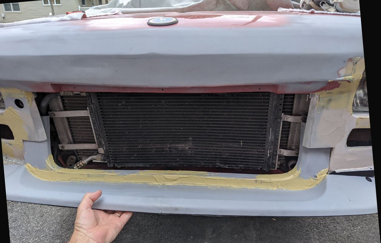
It was then suggested that I fill in the support to level it with the spoiler / fender skirt, and to resolve the inner fold of the vertical support that I hadn't figured out yet
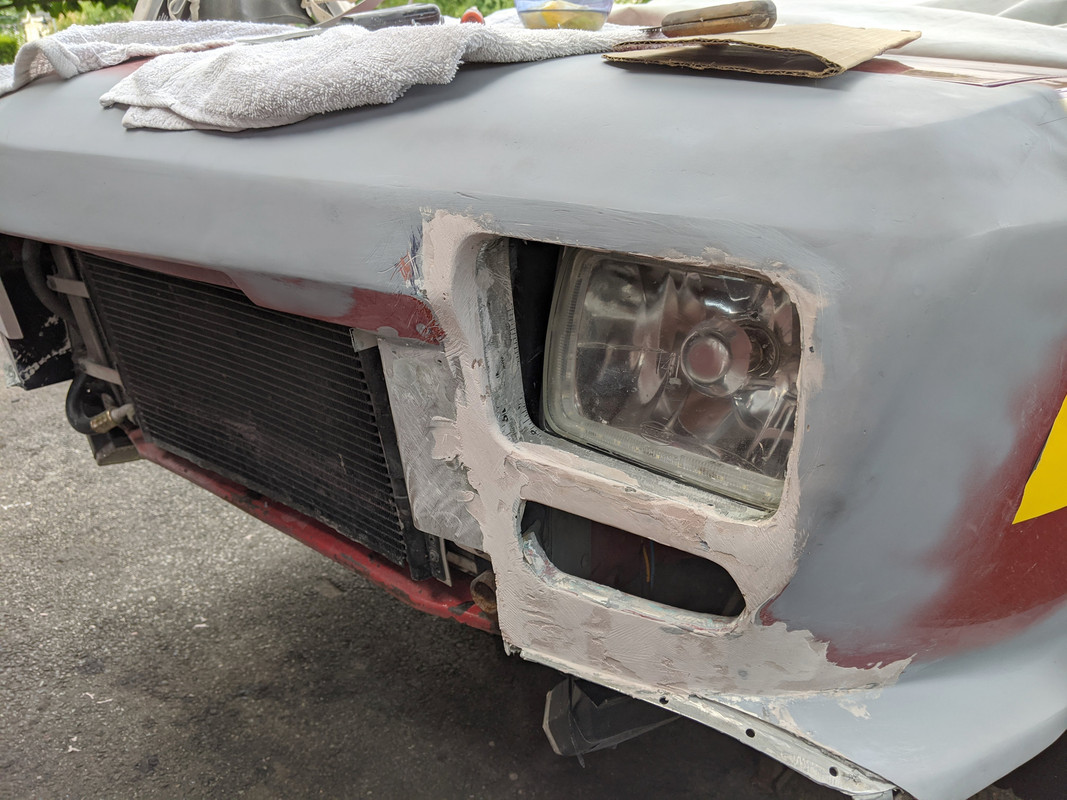
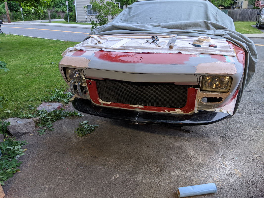
some skim coats of filler later
followed by several more rounds of fill, sand, repeat. Some details to finalize, however it's pretty much where it needs to be, finally!
lastly, cut up a V70 air guide

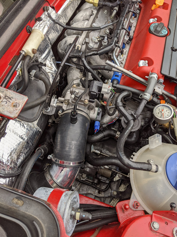
Also revised the TB setup to resolve the jerky tip-in part throttle drivability issues. Replaced the 80mm TB with a 72mm
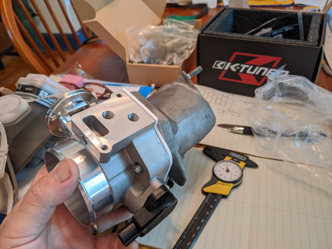
made a new plenum adaptor to fit it - didn't want to rework the plenum itself, as it barely can be removed in the car as it is - adding to it would make it impossible

made a bung for the MAP
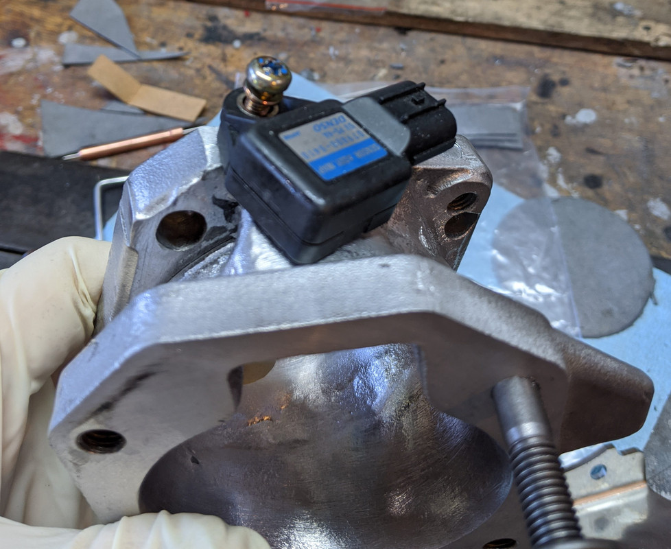
test fit the TB
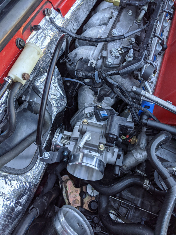
revised the connection to the air filter - used some of my left over (from the XR) pieces of IC piping & tubing to make the transisiton

some issues with the TPS - turned out I didn't have the correct RSX Type S version, which has a reversed offset vs. other models - this is where it needed to be to get 0º throttle opening in the software - not good
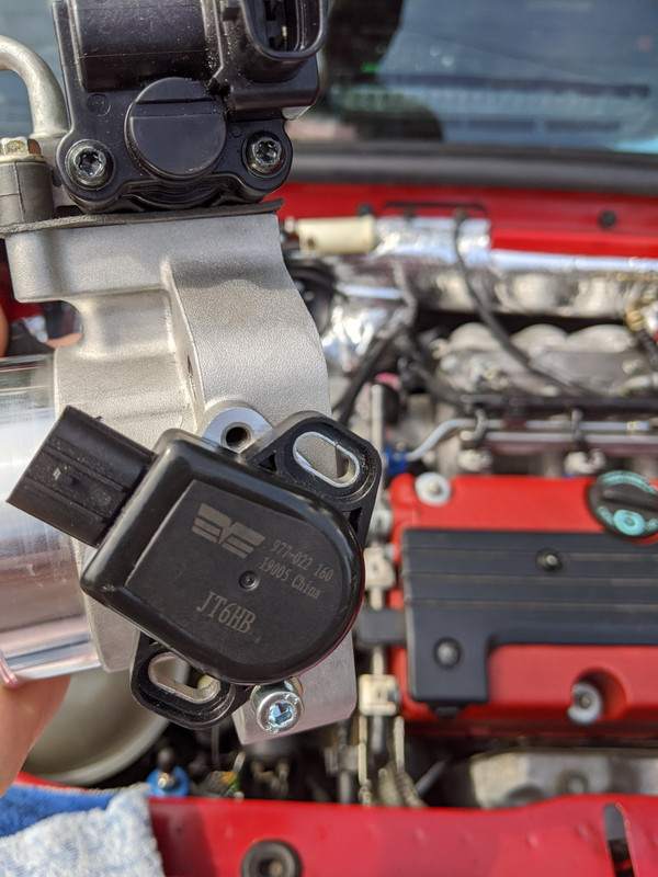
ordered the K-Tuned one, since it's meant to go with this TB - comes with a fancy billet cover, which I don't need & can't use with my space limitations

All done & back together.
-
 1
1
-
-
7 hours ago, Simply Volvo said:
I planed on just suspending it off the hard lines... or orienting it and mounting it with a u bracket to the steering rack.
The pump is a 2-4 psi low pressure fuel lift pump for a carb. Its self priming and can lift 18". Its a diaphragm pump that uses a solenoid to pull and push on the diaphragm so I am not too worried about vibration effecting it... its very very basic with very minial moving parts (diaphragm and check valve balls).
I will also have both a pressure sensor (to determine pump failure) and oil temperature (to determine heat soak) integrated.
Sounds like you have it covered - I do think if you use any sort of mount bracket it need to be on the drivetrain, so it can move with it under load. Putting it off the rack sounds like adding more stress to the lines, unless you make them longer & allow for the drivetrain arc under load.
-
How are you finalizing the oil feed system? Is the pump going to be suspended off the lines, or are you making a bracket to anchor it to the AG? In all likelihood it's probably OK hanging off the rigid pinion line, however I would worry about vibration affecting it over time. What failsafe will you have to monitor the pump over time, or is it intended for the harsh automotive environment?
-
Coming along nicely. So much crap to organize w/AWD.
To save yourself some grief - DON'T use copper/alloy line for the exhaust back pressure setup - it will fail. Use stainless brake line & stainless fittings
Also make sure to add a water trap, or the condensate will kill whatever sensor/gauge you use overtime

-
1
-
-
CONGRATULATIONS!!!!!!
-
Why not just make a short feed line from the surge tank to the line you already made? Then you wouldn't need to run a new line all the way to the FPR/rail....
-
Nice! I really missed not going to Carlisle this year
 - Between having to look out for my 80 year-old Mum, and my wife's concerns, I decided it would be better to skip this year. Will you be going to the EUmeet outside Ithaca in Oct? That I will be attending.
-
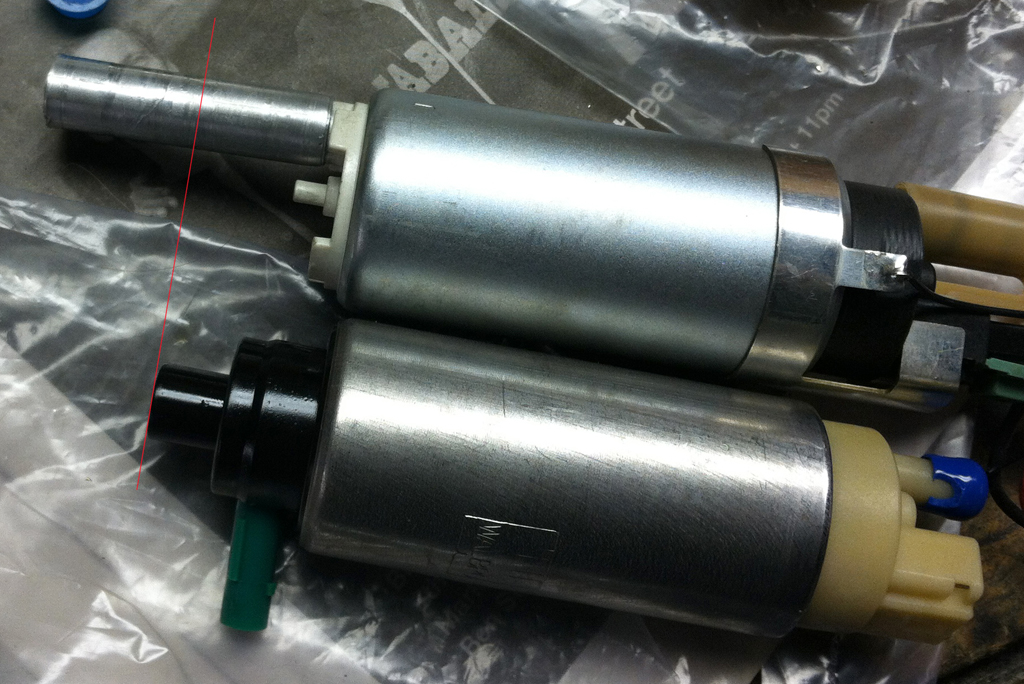
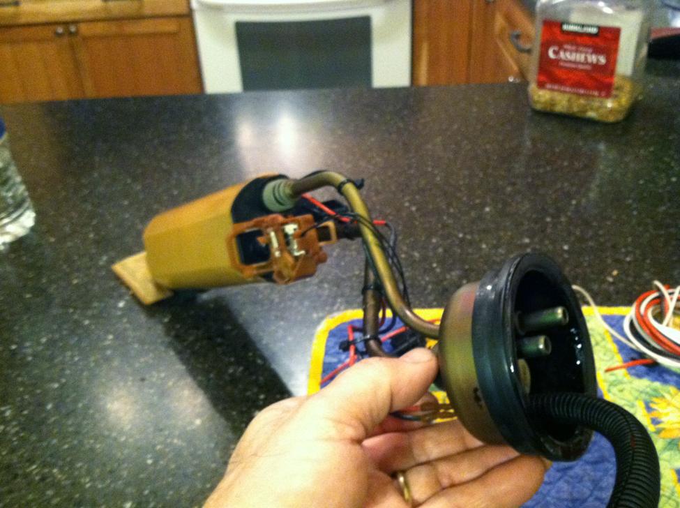
I wouldn't use corrugated tube - I did try that for a couple versions - the corrugations are not helpful for oil foam
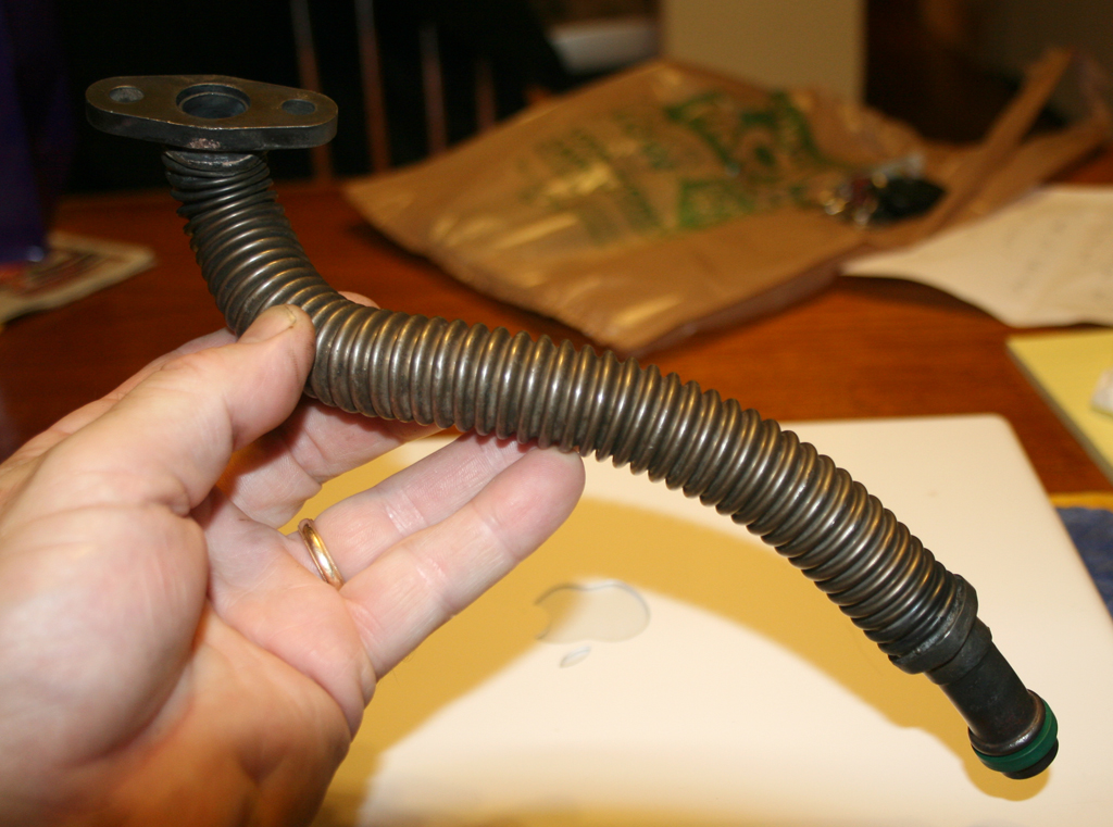
I just found a piece of thin wall aluminum tube that was a snug fit over the inlet - I never made a note of it, sorry
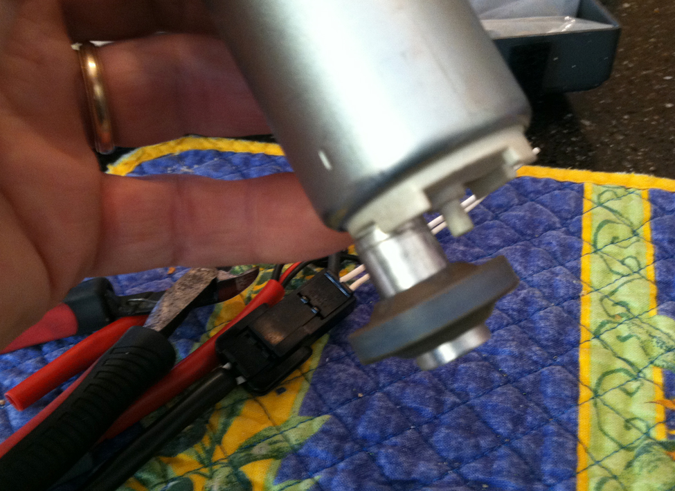
Add the safety ground sleeve - and + - are reversed.
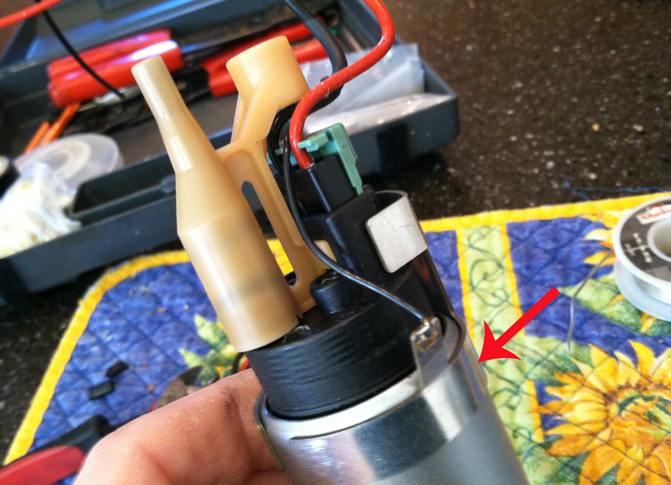
Cut a small opening in the underside of the case near the bottom (not shown), since the DW has no secondary pickup for fuel residing inside the pump housing
-
1
-
-
Nice work! I could have told you better to check the freeplay / movement in gears using either the assembled AG, an axle or even an old clutch disc- as you found, hold the input shaft you don't have enough leverage to overcome the gear ratios

With the oil drain, better to avoid 90's - if you can keep a slight downhill all the way it's gonna be better - remember that you are dealing with oil foam when running high load/rpm, not just oil flow.
-
 1
1
-
-
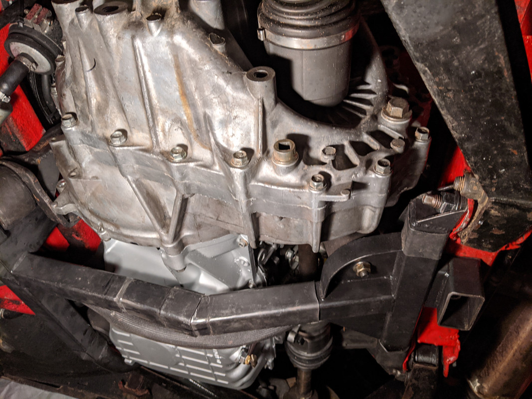
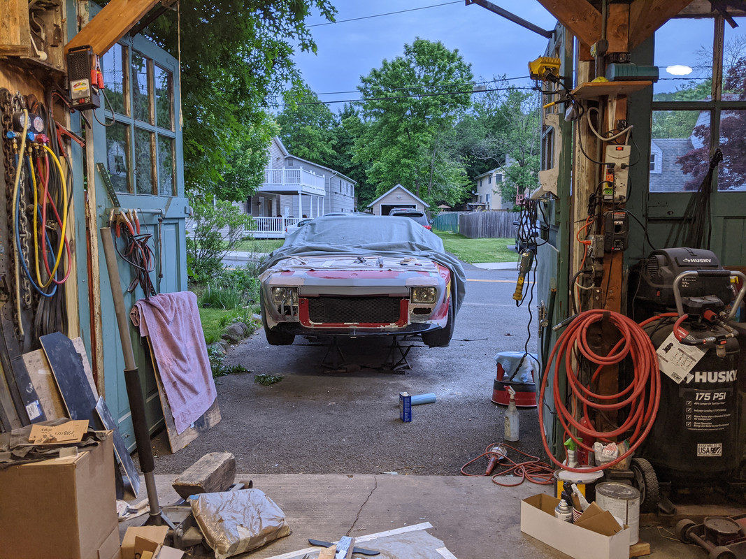
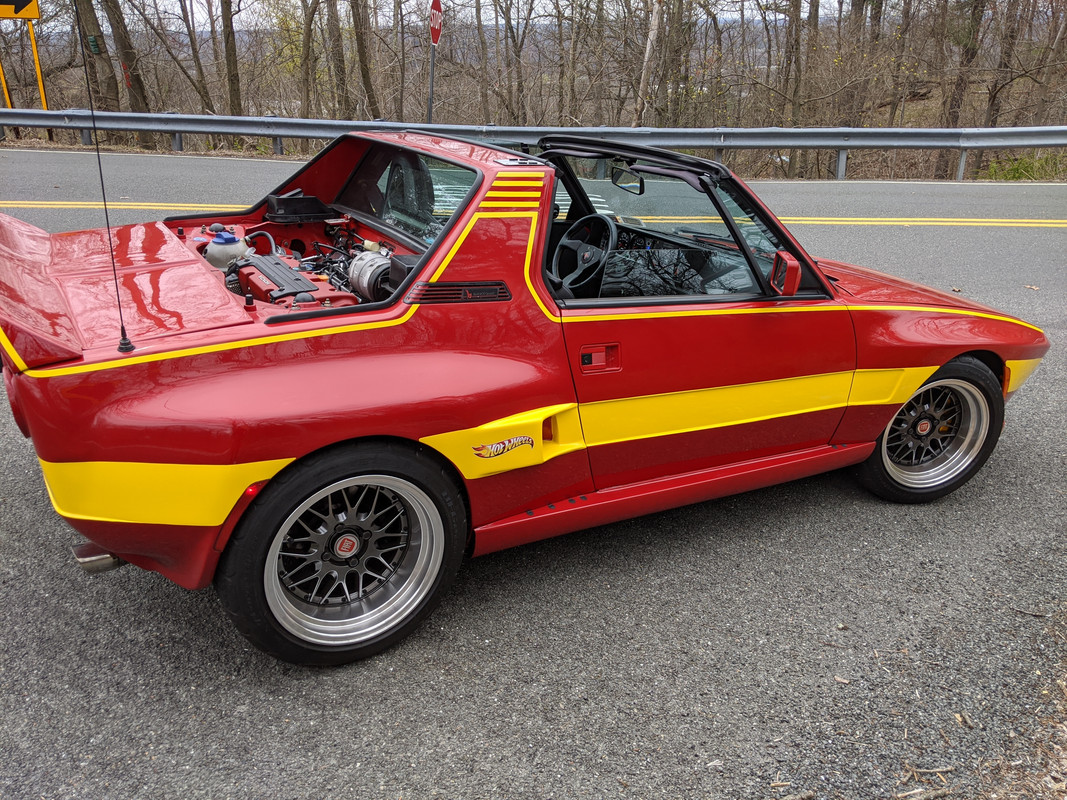
Wrapped up the nose for right now - and moved on to the mechanical work needed to get it running. Dropped the subframe, swapped the oil pan, tack welded the replacemnt subframe section & took the car out for a drive for the first time in 3 monnths!
replacement, and new brake line I had to fabricate to replace the one crushed


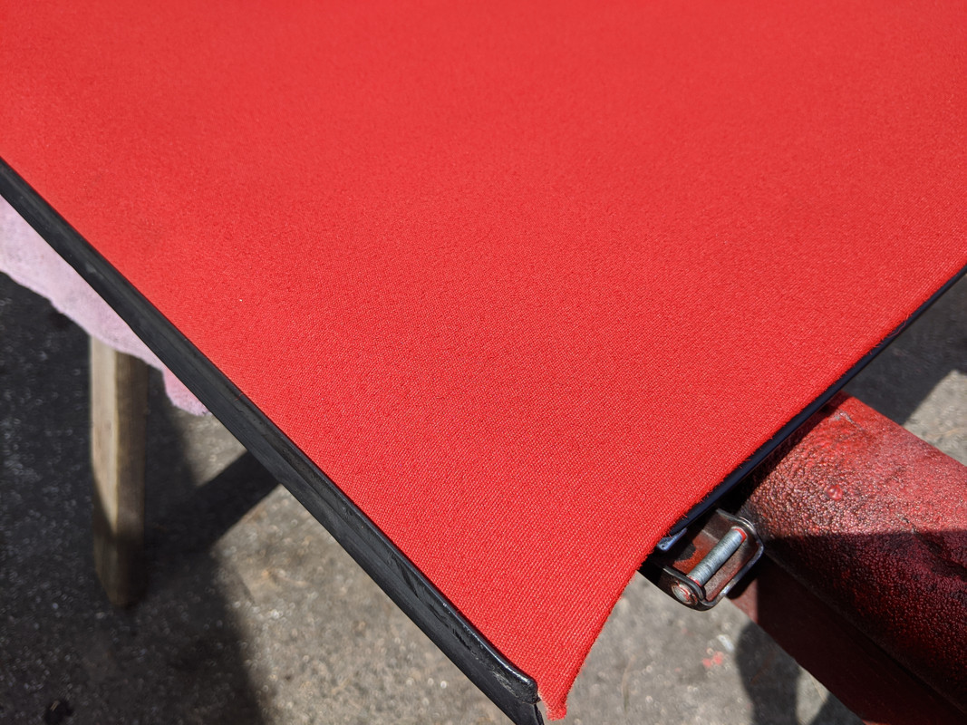
Also painted/dyed the canvas targa panel

-
5
-
-
6 hours ago, apeacock said:
I also hope to not see that work again!!! and yes it's horribly messy.
There are two types I used on the car and they both work well. For this stuff I used the TESA tape https://www.ebay.com/itm/TESA-51628-ADHESIVE-PET-FLEECE-WIRE-HARNESS-TAPE-3-4-X-25M-CLOTH-FRICTION-FS/232987963975?epid=10026590887&hash=item363f2a3247:g:s7gAAOSwgjFZuBZ3 show in there.
There's also a super excellent tape (how great can it be right?) That's Coroplast Automotive tape. its part number is 837x (https://www.ebay.com/itm/181949537255?ul_noapp=true) and it's the stuff. You can't tear it and it's bond is really impressive.Many thanks, Anthony! I bought some of each, I like to have good quality tape on hand. What I have done in the past is unwrap the factory cloth tape from salvaged harnesses - but that is a royal PITA ....
-
Nice work!
Fiberglass work is a little messy - but no -one's ever going to see that
Do you have a PN for that tape? It looks the same as the stuff used to wrap the P1 harnesses - I could use some of that in the cabin
")
-
Dang Matt - once those height pins started bending, you should have stopped using that press. Very lucky you didn't kill yourself dude. IF you do repair the jack for jobs under 20 tons, I have found that the x70 AWD axle shaft fits in the press frame height holes. I cut a pair of dead axles down to a suitable length & use them with my 20 ton press. Much better steel than the HF-supplied crap. I appreciate that you document mistakes, it is all part of the process & I dislike videos where they zip over the actual steps & hide mistakes. Better to be honest. However you REALLY need to take care of yourself first!
-
15 hours ago, tighe said:
Wow, yeah. Very glad it wasn't worse though! @lookforjoeHow does the car handle in general? Pretty predictable, or is it a wild child?
It's like a go cart - it basically goes where you point it. It's really fun to drive. I don't know about the upper cornering limits - I didn't get to drive it that hard yet. The problem with stock X1/9's is that they stick like glue .... until they don't, at which point the the rear will spin out on you. With front & rear sway bars added, the wider track & sticky tires I have found it easy to go through winding roads/exit entrance ramps at much higher speeds with very neutral handling. Even in the accident, I was able to steer it off the road to avoid the guardrail - just unfortunate what was in my path as I did so.
-
3 hours ago, gmsgltr said:
I am really sorry you have to go through all this front end work again - the work and documentation, as always, is awesome and fun to follow
Thank you. I'll be happier with the revised nose once it's done - simpler form, closer to orginal. The undercarriage damage, not really looking forward to that
-
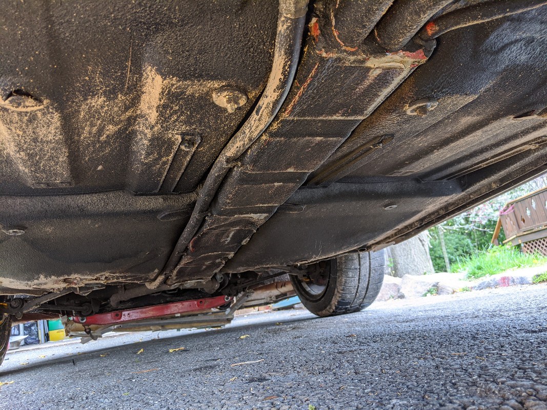
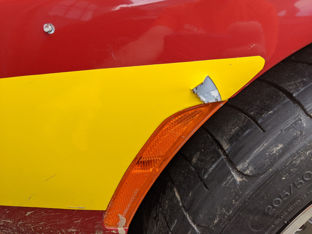
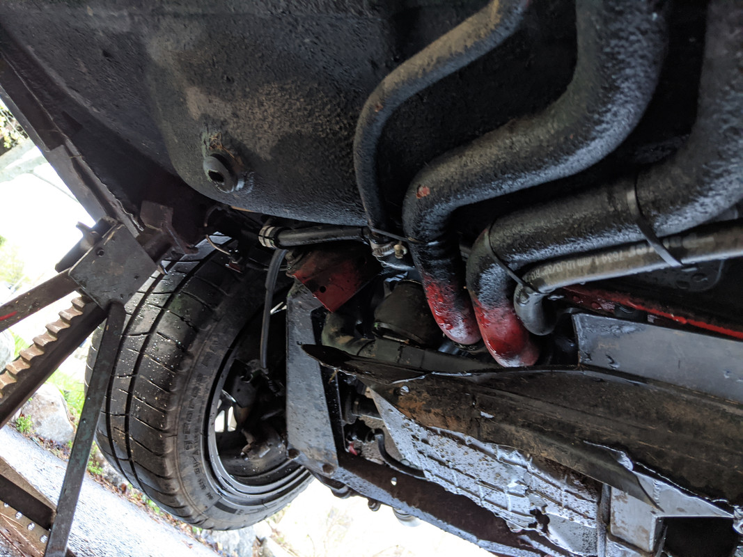
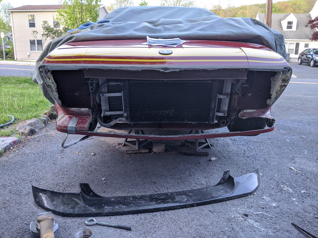
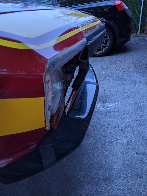
Car took a beating just over a month ago.
First, I drove it to work that morning, so I could log the part throttle & warm up issues. Poured with rain, so I was able to confirm no water ingress.
Finally resolved the drivability issues earlier that afternoon after reviewing the logs. Had to go buy a new battery also - my MT-24F was about 7 years old & no longer likes to hold a good cranking charge.
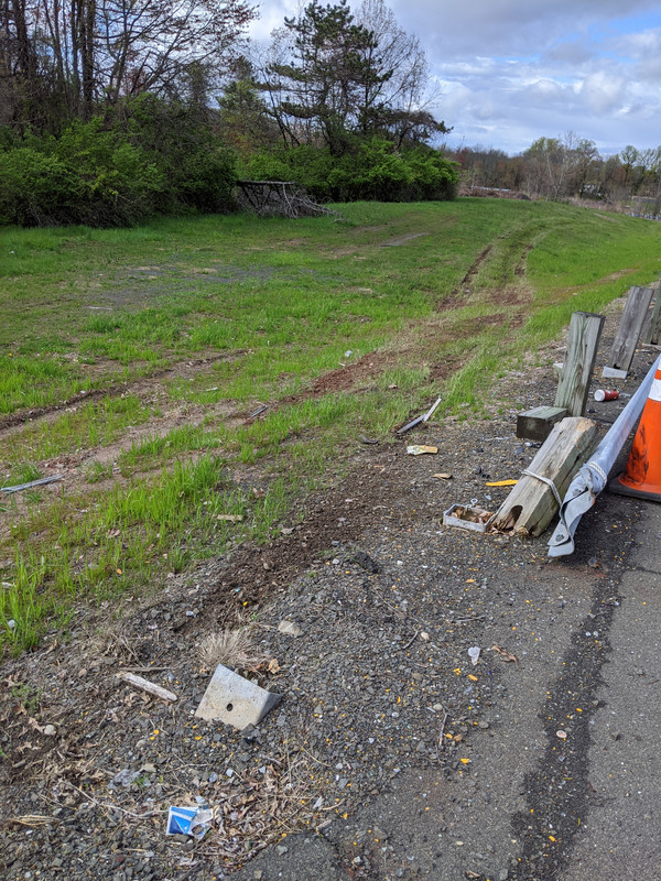
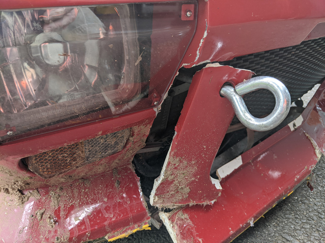
Coming home from the drive to confirm throttle tip in & part throttle issues were gone, I rode over some debris in the bend of the exit ramp for the NYS Thruway , and went sideways enough that I had to quickly decide whether to cut it hard & go right off the roadway onto the grass divide, or hit the guardrail.
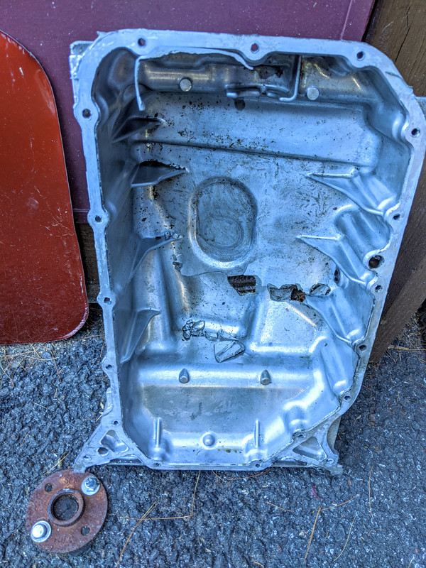
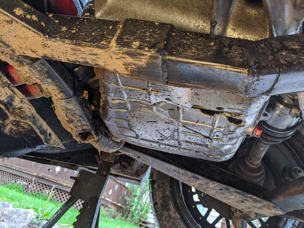
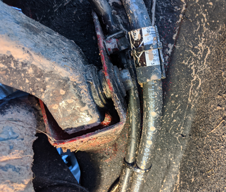
Unfortunately there was the remnants of a post base where I left the roadway and it tore off the front sway bar and ripped out the oil pan (I found out after I stopped). The car dipped into the gully & slammed the nose hard. I steered it down the divide & back into the shoulder & turned it off. I looked under & saw all the oil gushing out. I don't know if I shut it down in time, probably 15-30sec from time of impact to shutdown. No injuries, just a little beat up from the nose dive


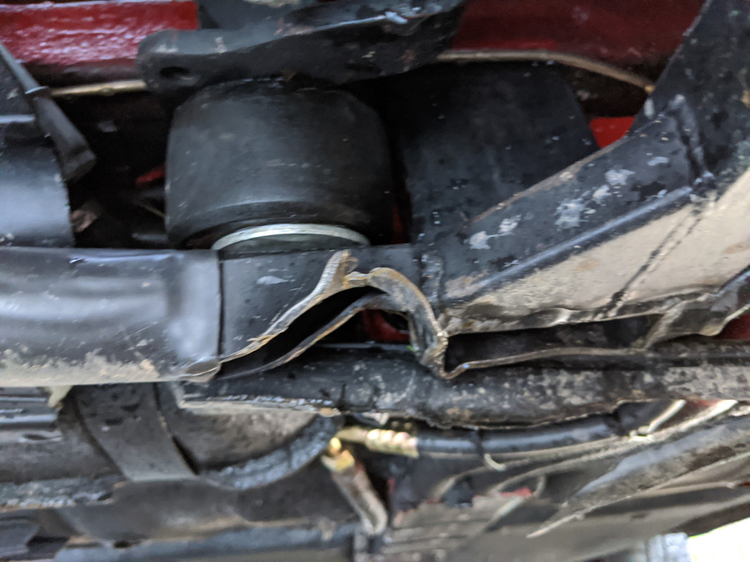
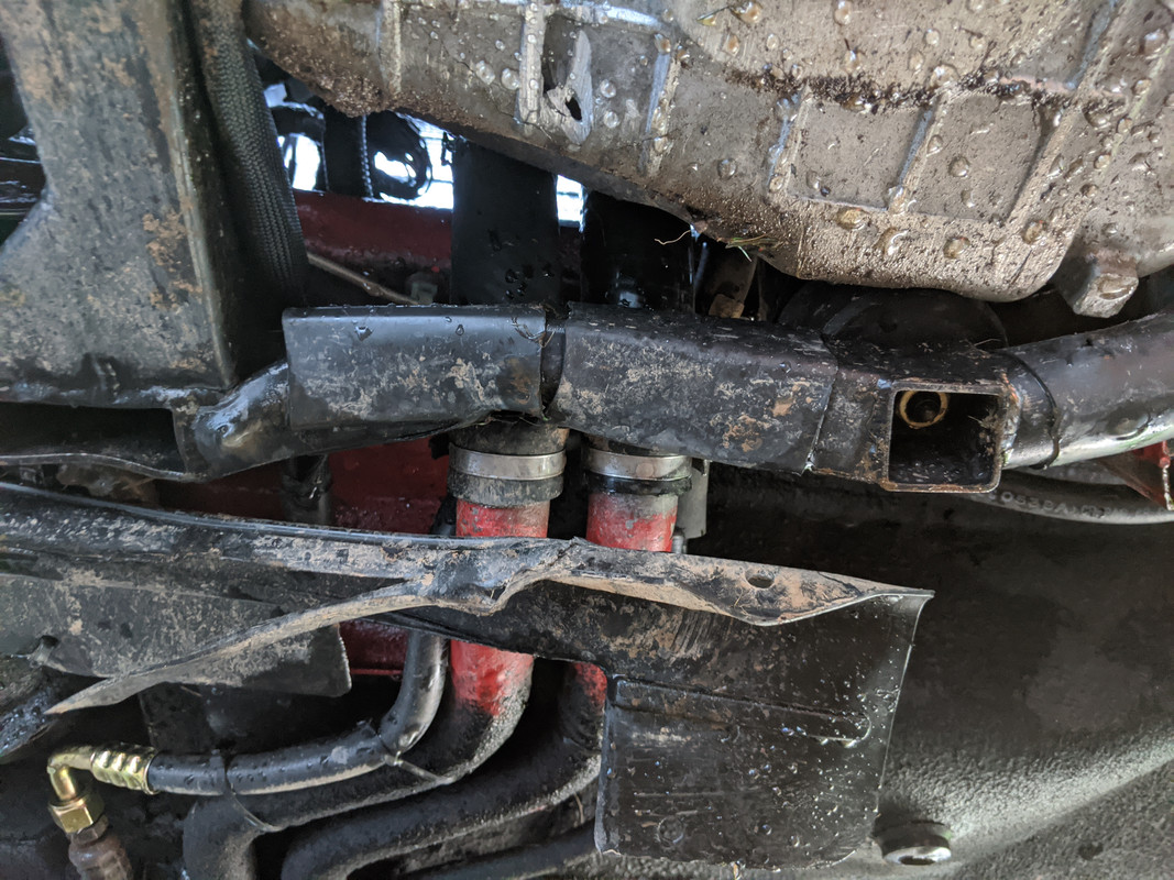
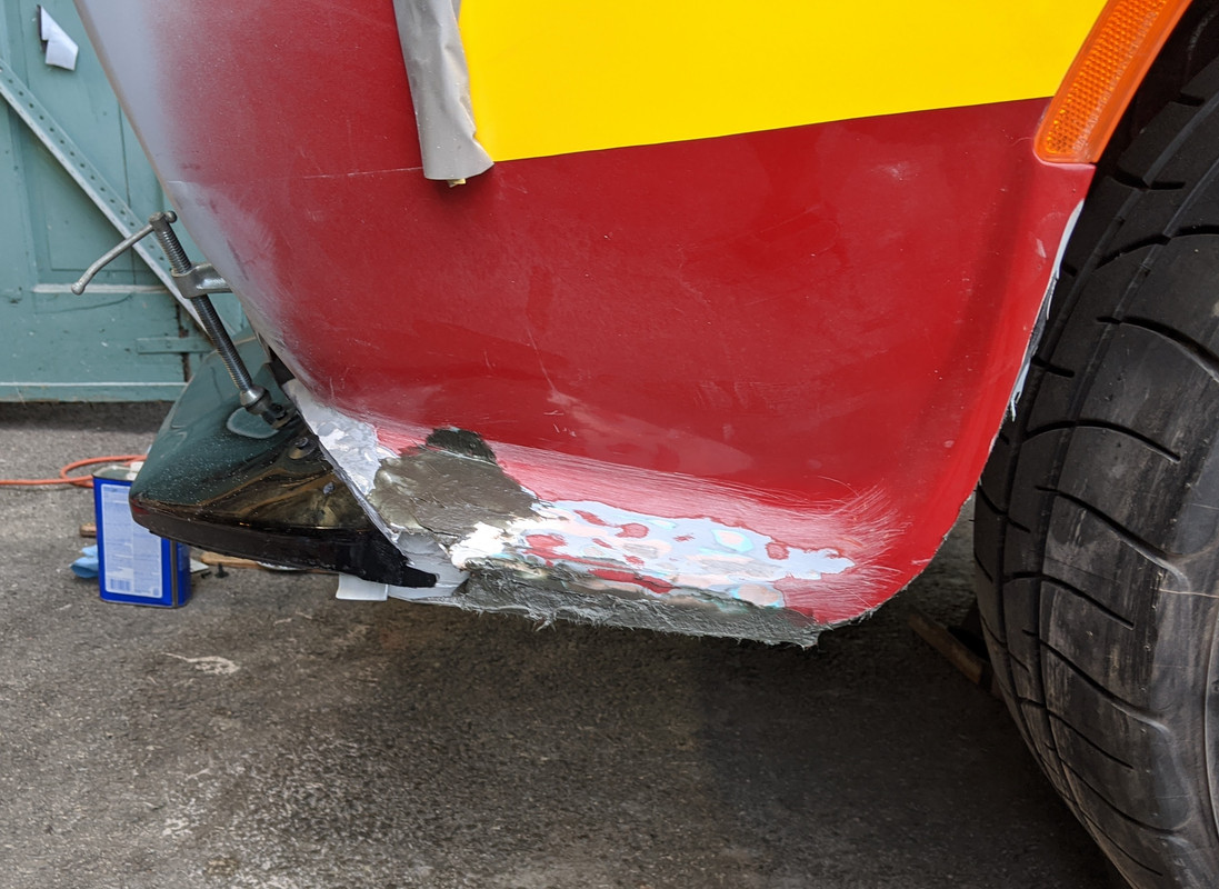
Center section took a hit
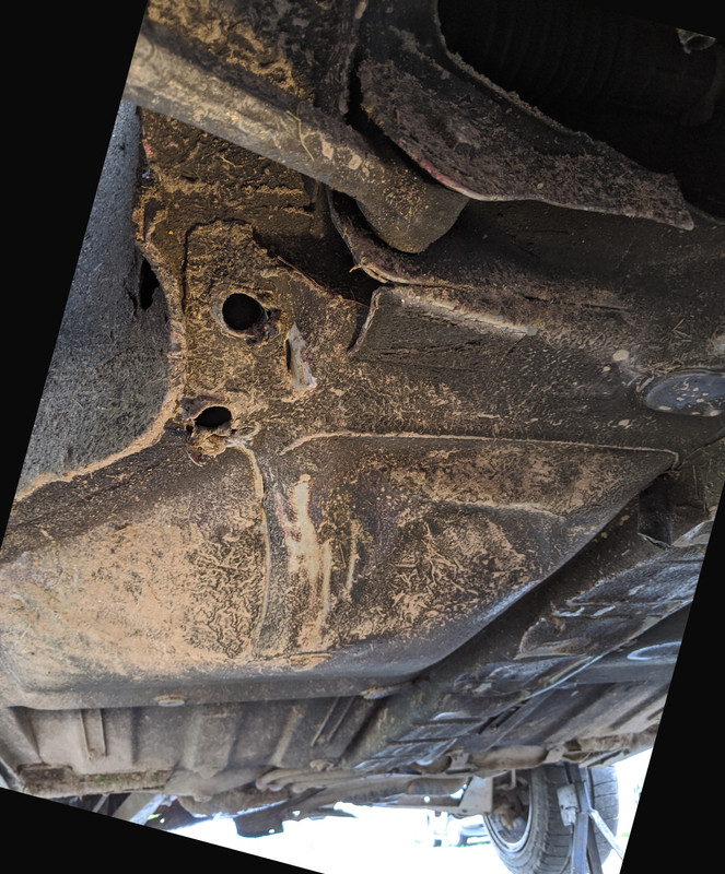
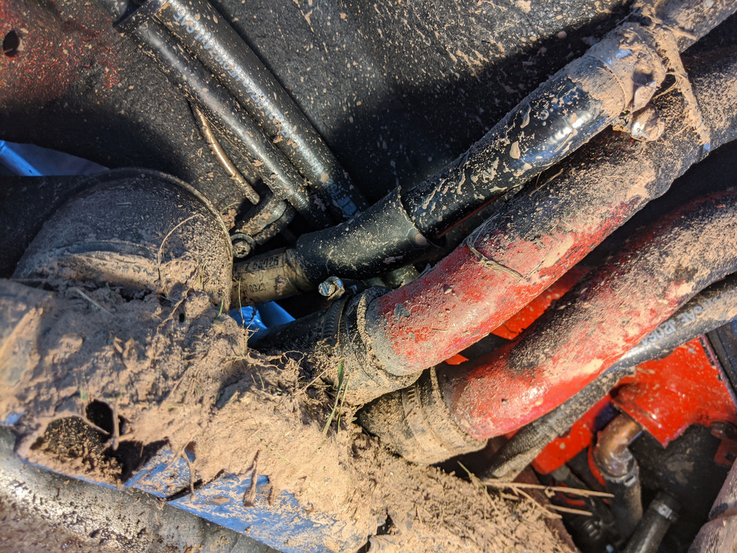
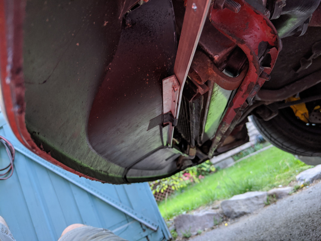
Water pipes pushed in, but not ruptured, cover peeled back, floor pans pushed in
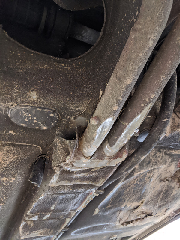
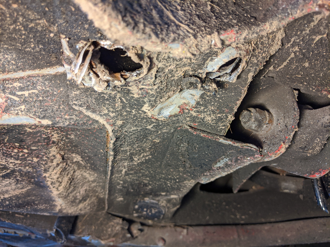
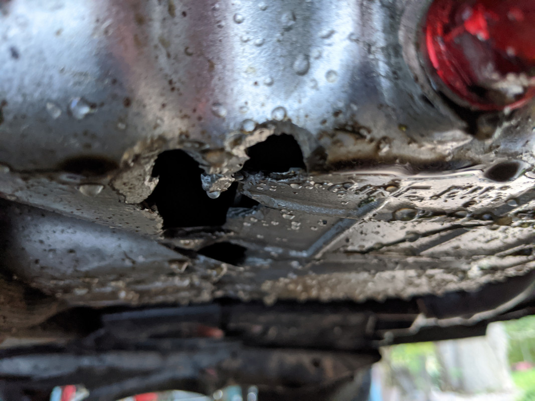
holes where the swaybar was ripped out
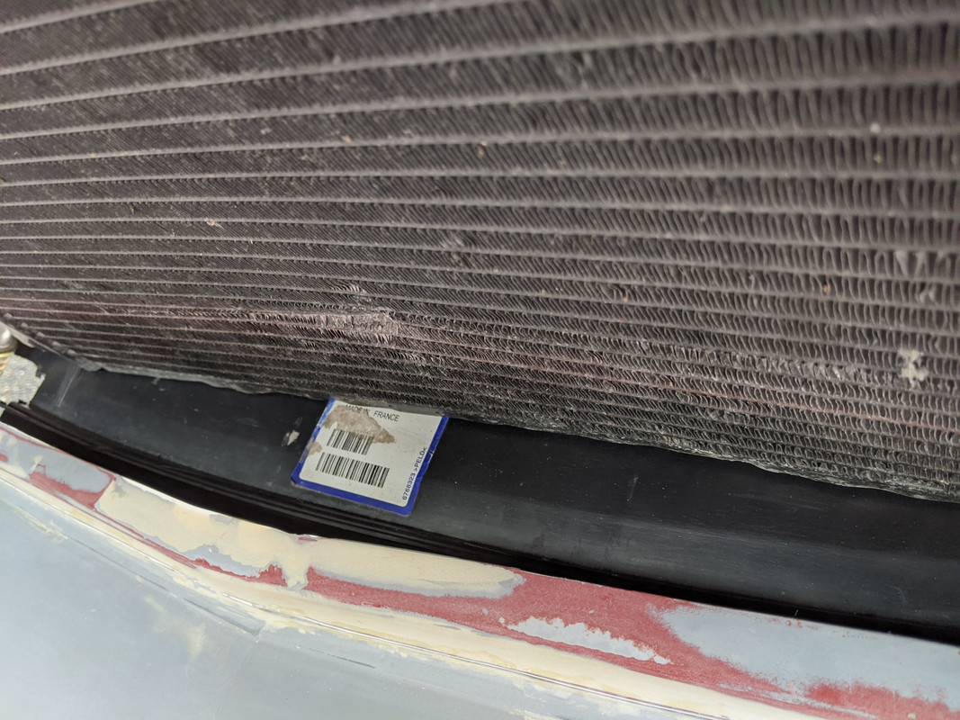
rad support pushed back - rad seems fine - AC condenser, not so much.
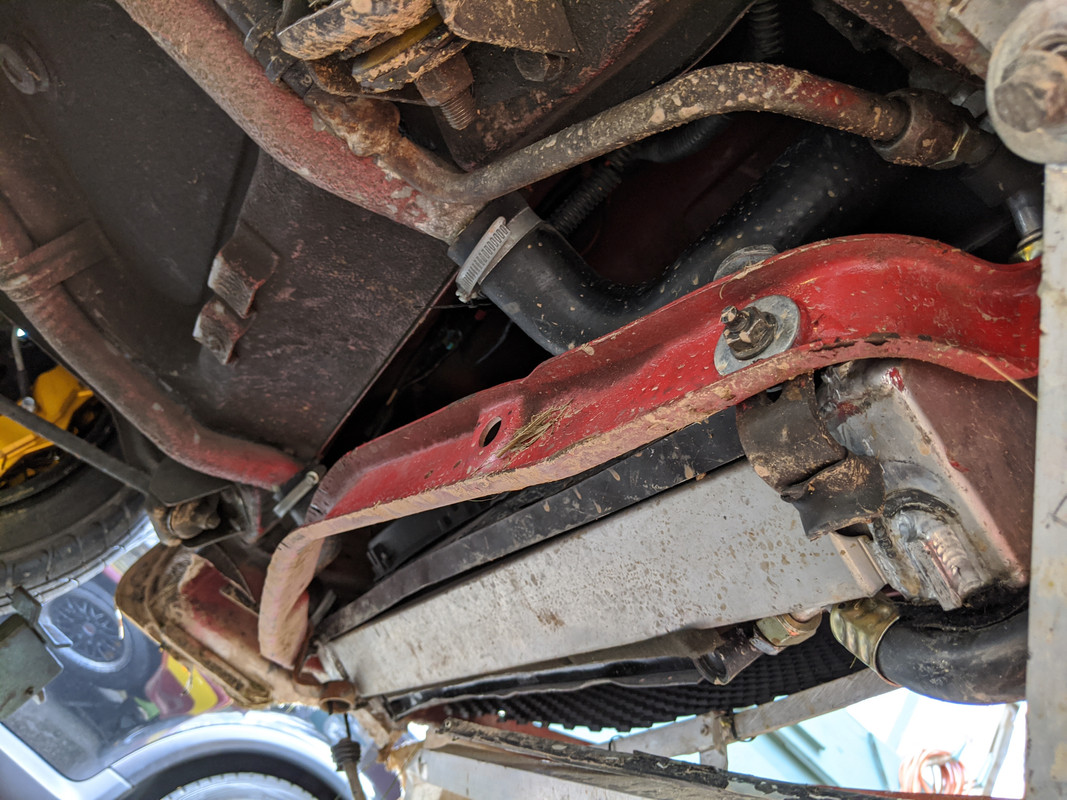
I think all the spoiler bracing I added helped mitigate the damage, as that must have absorbed some of the initial impact - after all, the entire nose didn't explode on me.
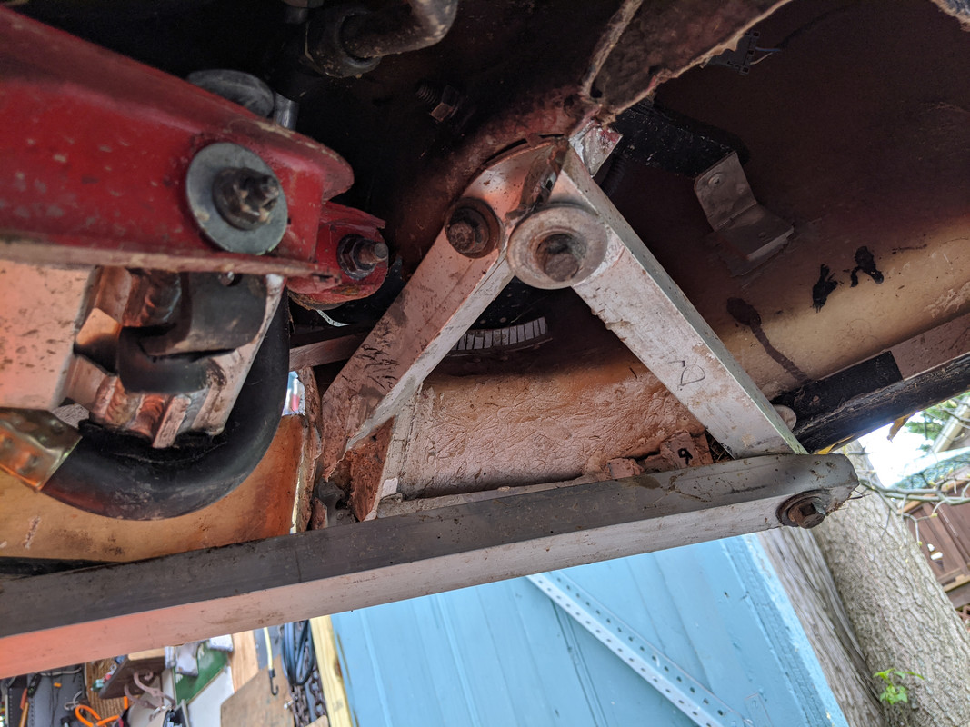
forward k20 subframe bent - pan ruptured, but not pushed in. so oil pump & baffle kit should be OK
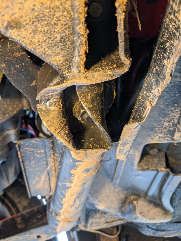
Mount ears 'look' OK - I'll find out when I take it all apart.
I'll be welding the cover panels instead of bonding next time
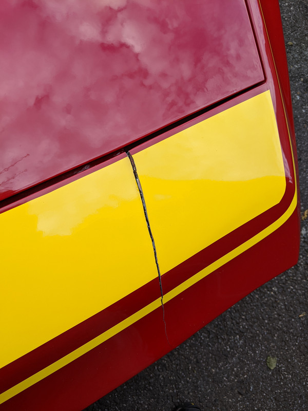
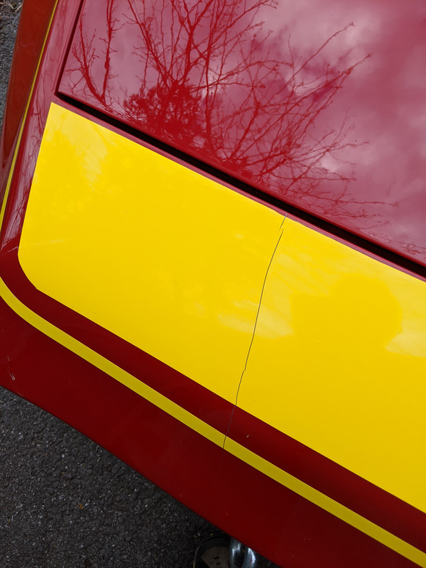
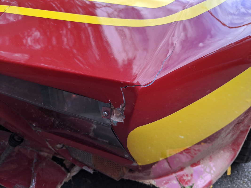
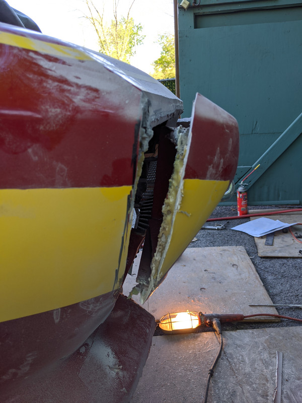
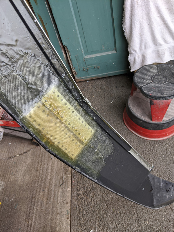
crack in fiberglass, popped the rivet plug, stress fractures in the glass above the strip
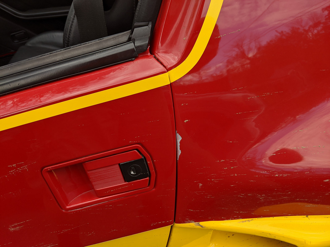
Door shunted the post
Further damage from the drop off the tow truck
Cleaned the car & undercarriage to remove all the mud. At least it looks good from the 3/4 views

Started on the nose. Chopped off a couple inches to get beyond the worst cracks
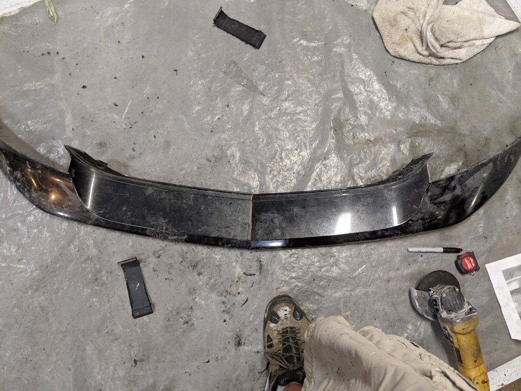
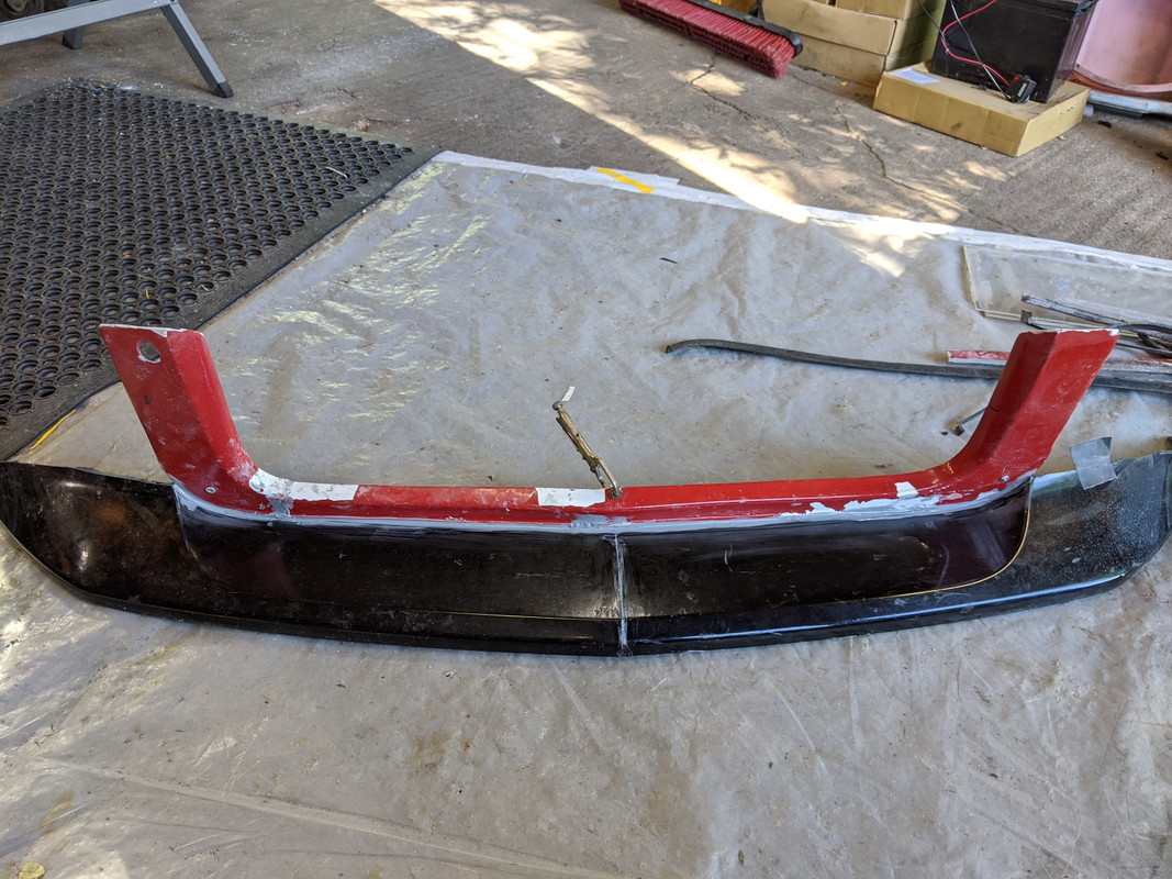
Took an S40 rear bumper cover
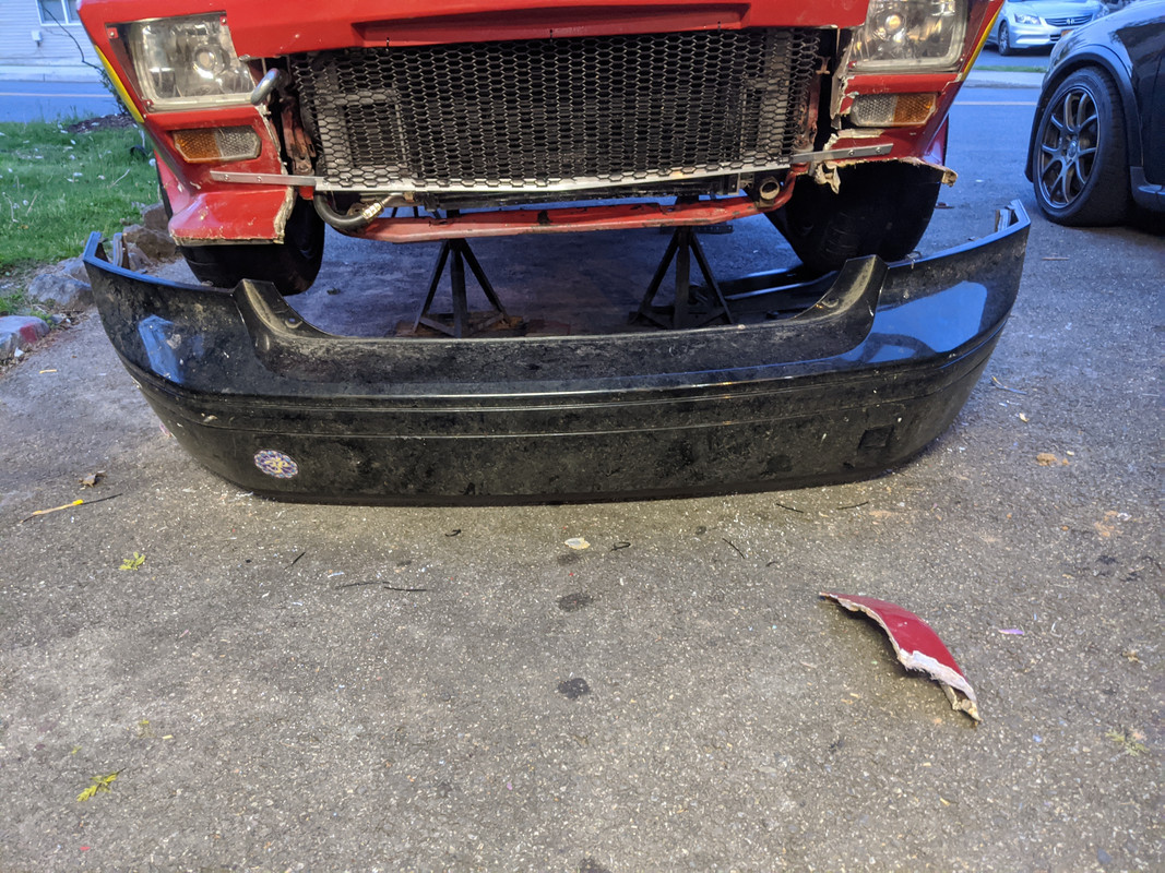
chopped off the top
sectioned the cover, and angled it to match nose, about 12º
Cut the grille surround off what was left of the fiberglass spoiler.
All that will be bonded together & merged into the fenders. Along with fibreglass panels around the headlamps back into the fenders

The underside will have some reinforcement, just to keep the contour from dropping
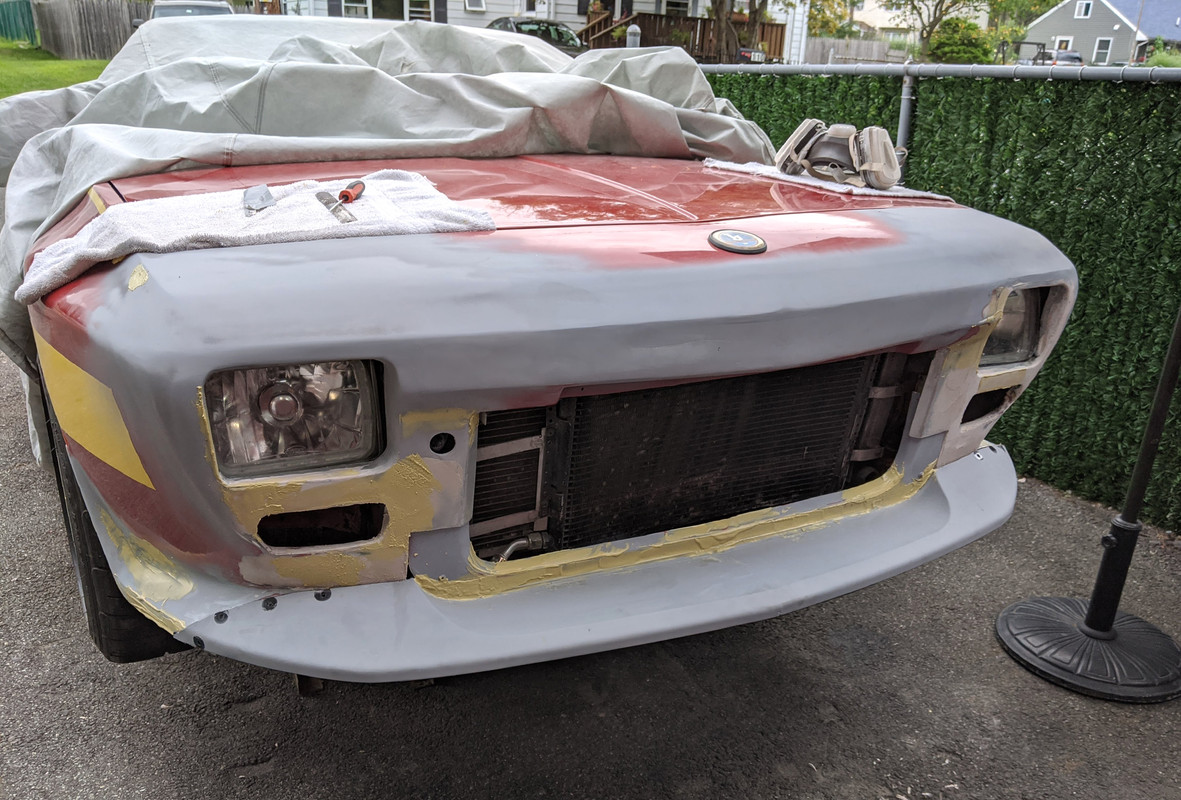
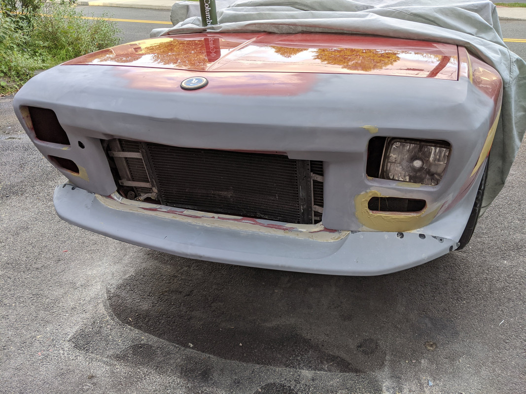
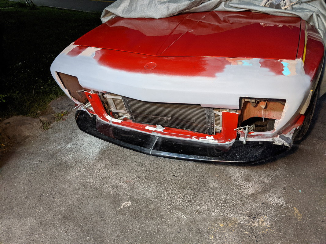
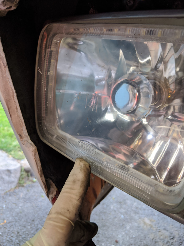
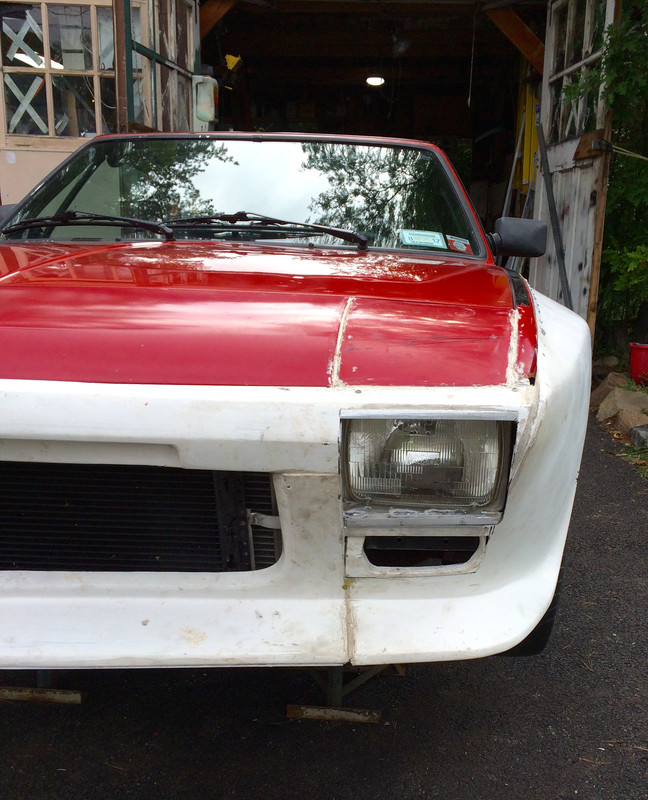
Plugging away at the nose repair. Got the sheet metal HL cover panels welded & filled. Worked on the nose / fender / grille transitins to get it all to flow nicely with the chopped version. S40 bumper section is going to work just fine for the spoiler.


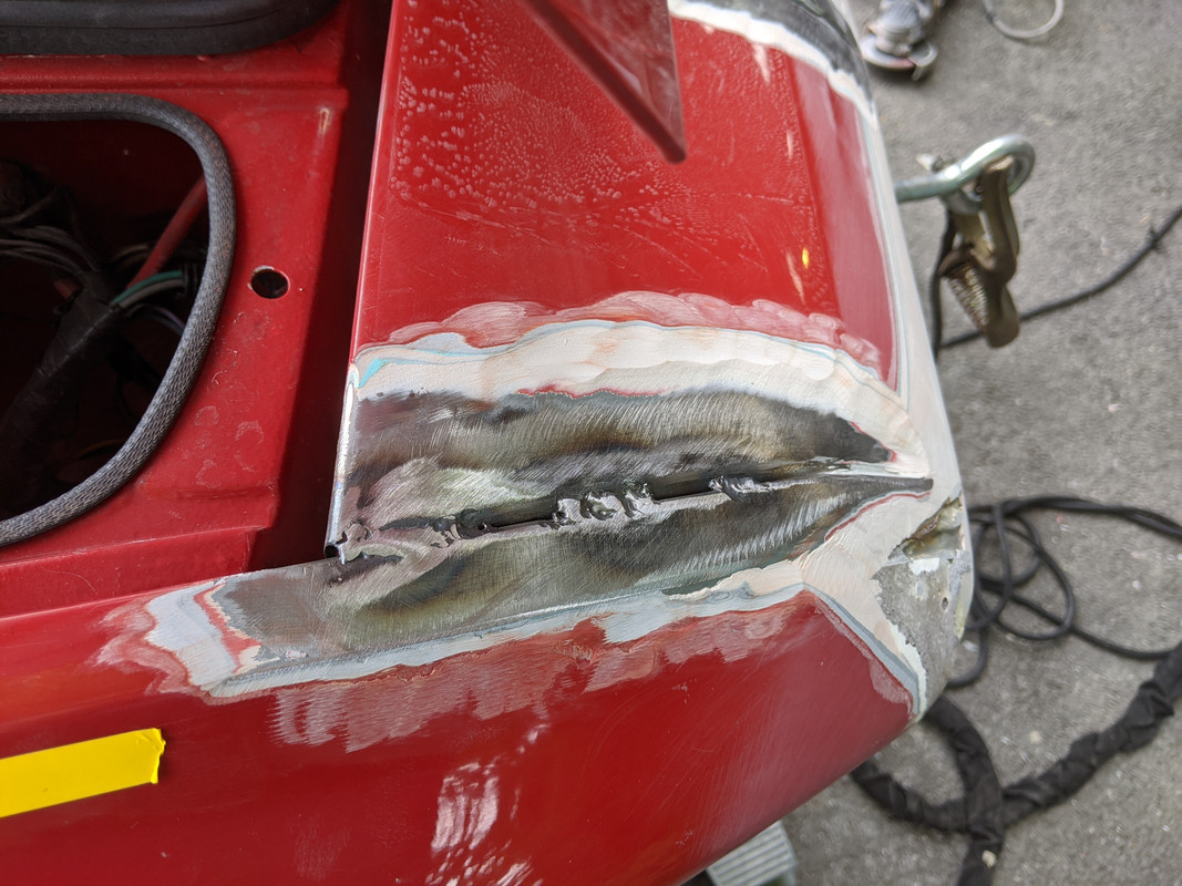
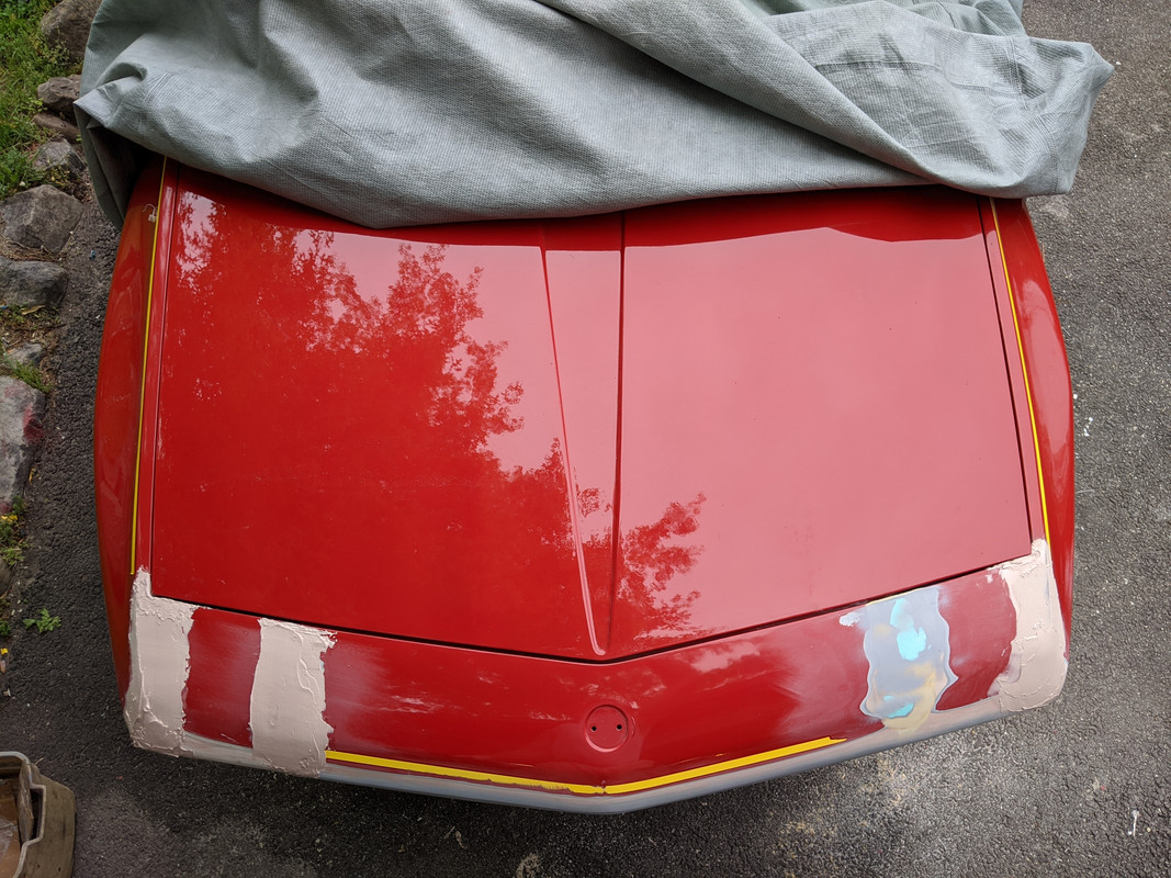


The spoiler/grille surround will be removable, so I need to figure out the mounting for the inner verticals, and make separate headlamp framing that is attached to the frame instead of to the grille surround as it was previously.

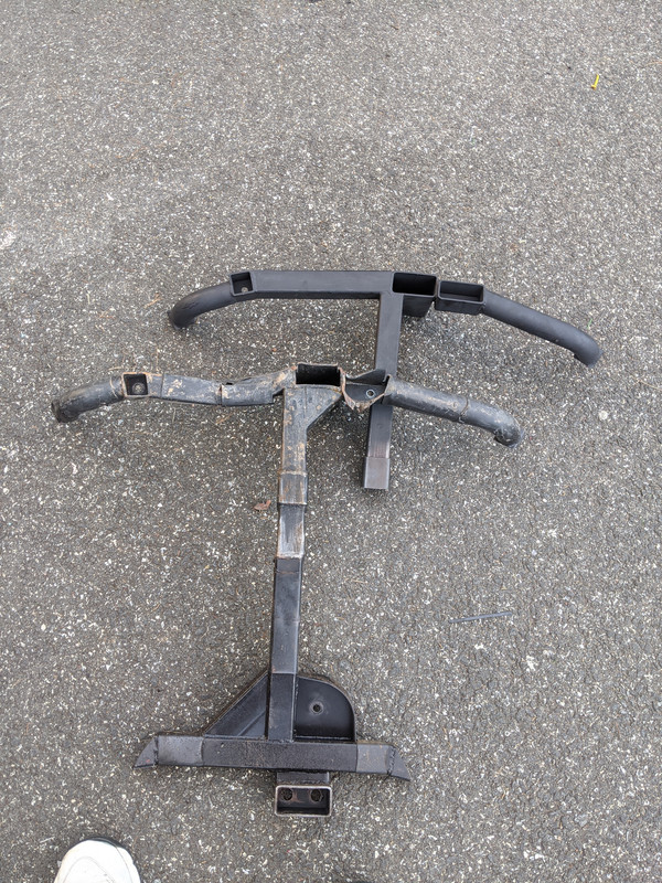
Subframe section has been completed
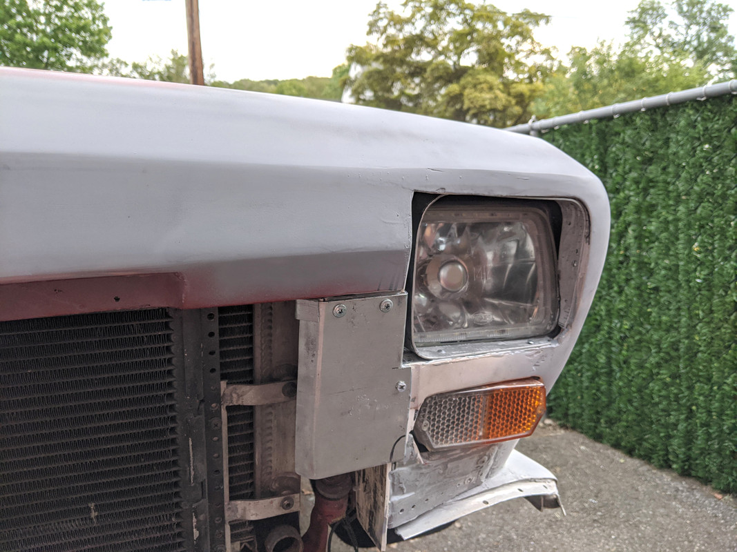
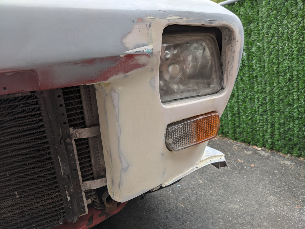
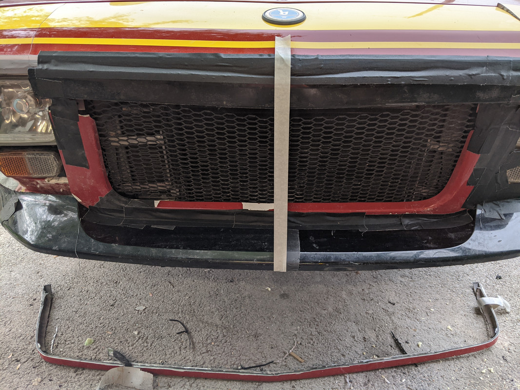
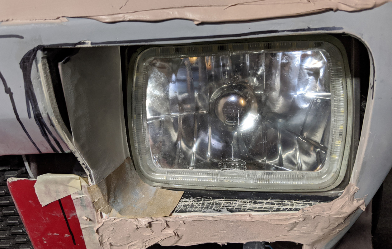
More back & forth (add material/remove material) on the nose & headlamp 'bucket' areas. Ideally, the surrounds should look similar to this:
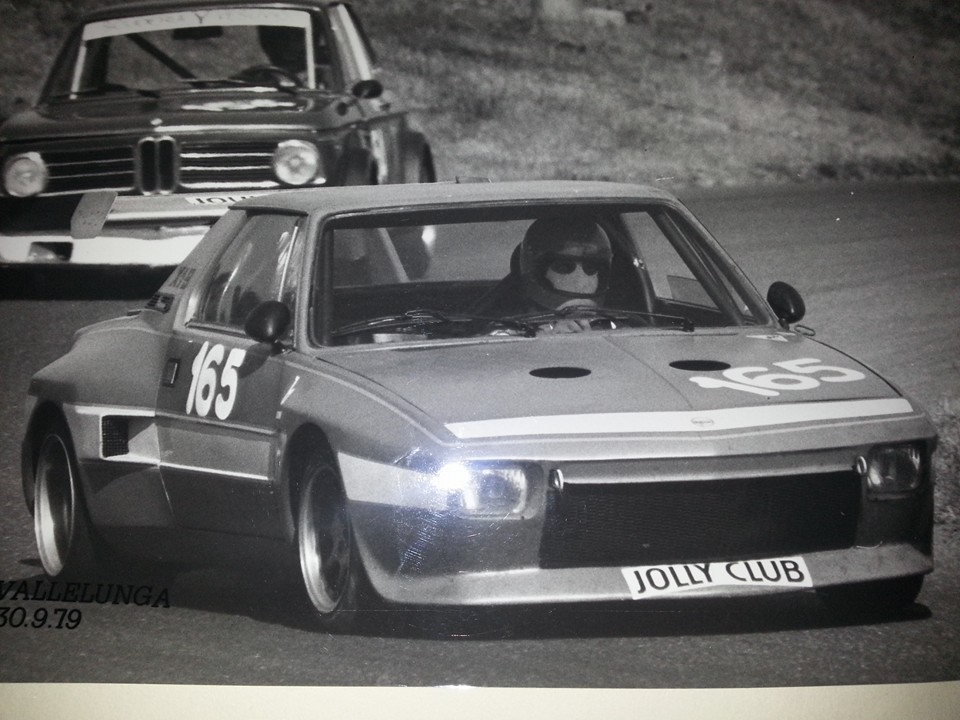
The difficulty is in getting the interpretation of the inner vertical 'scallop' - my center panel is not the same as the original - I don't have the setback & taper that matches - mine is vertical drop, then chamfer - so my version is to be an interpretation of the original.
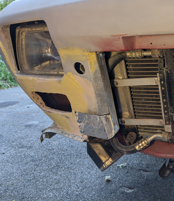
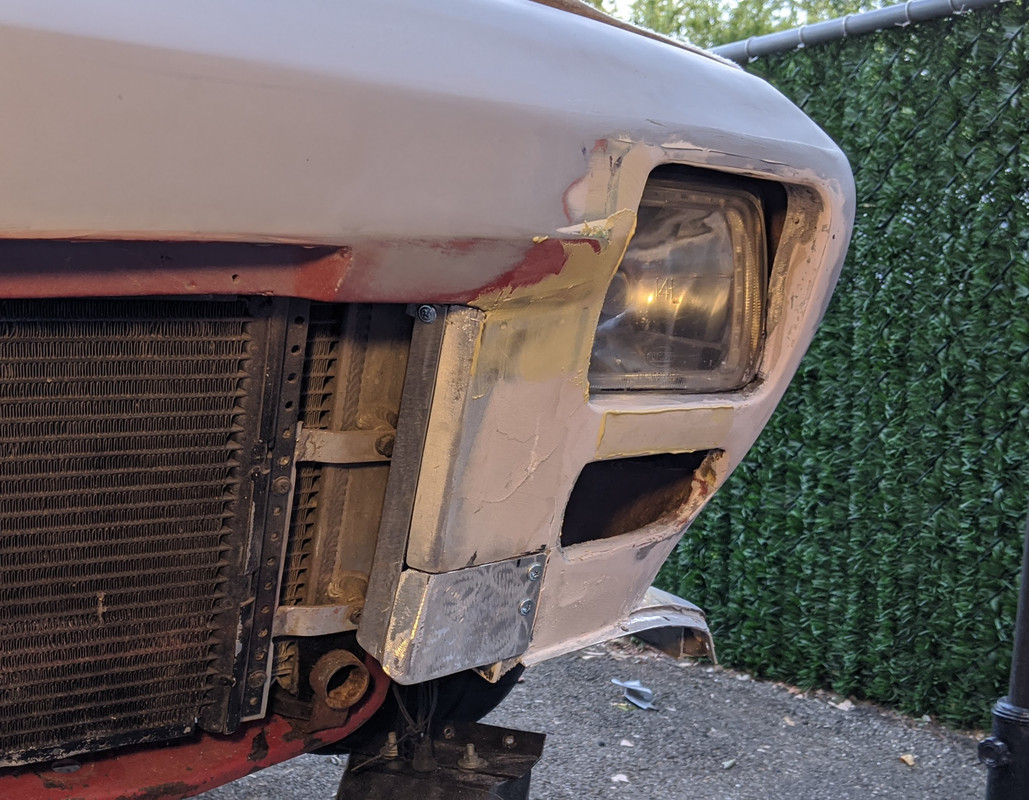
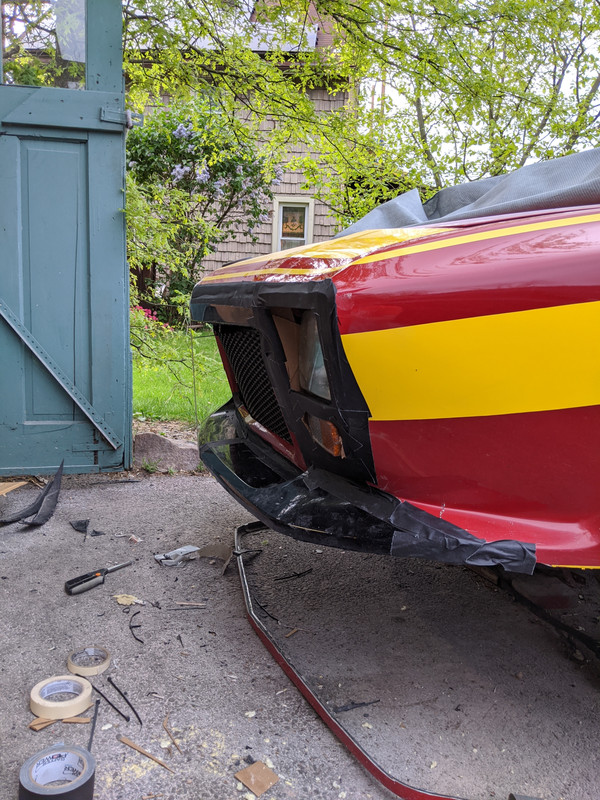
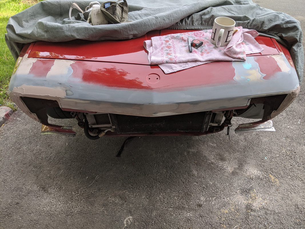
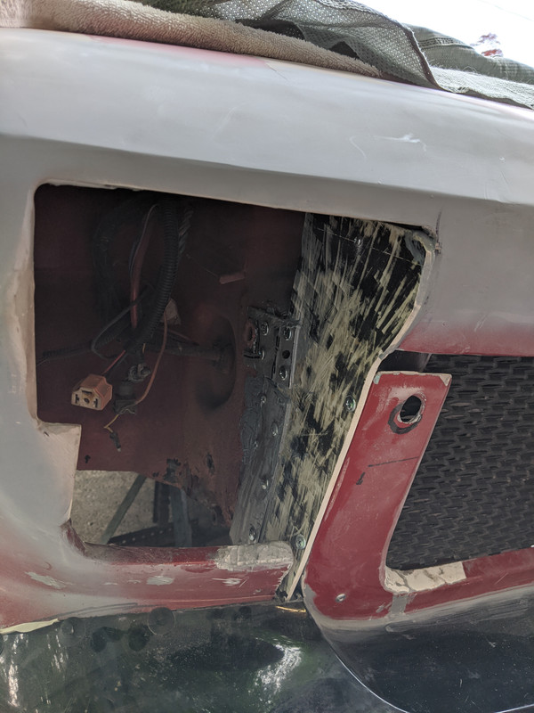
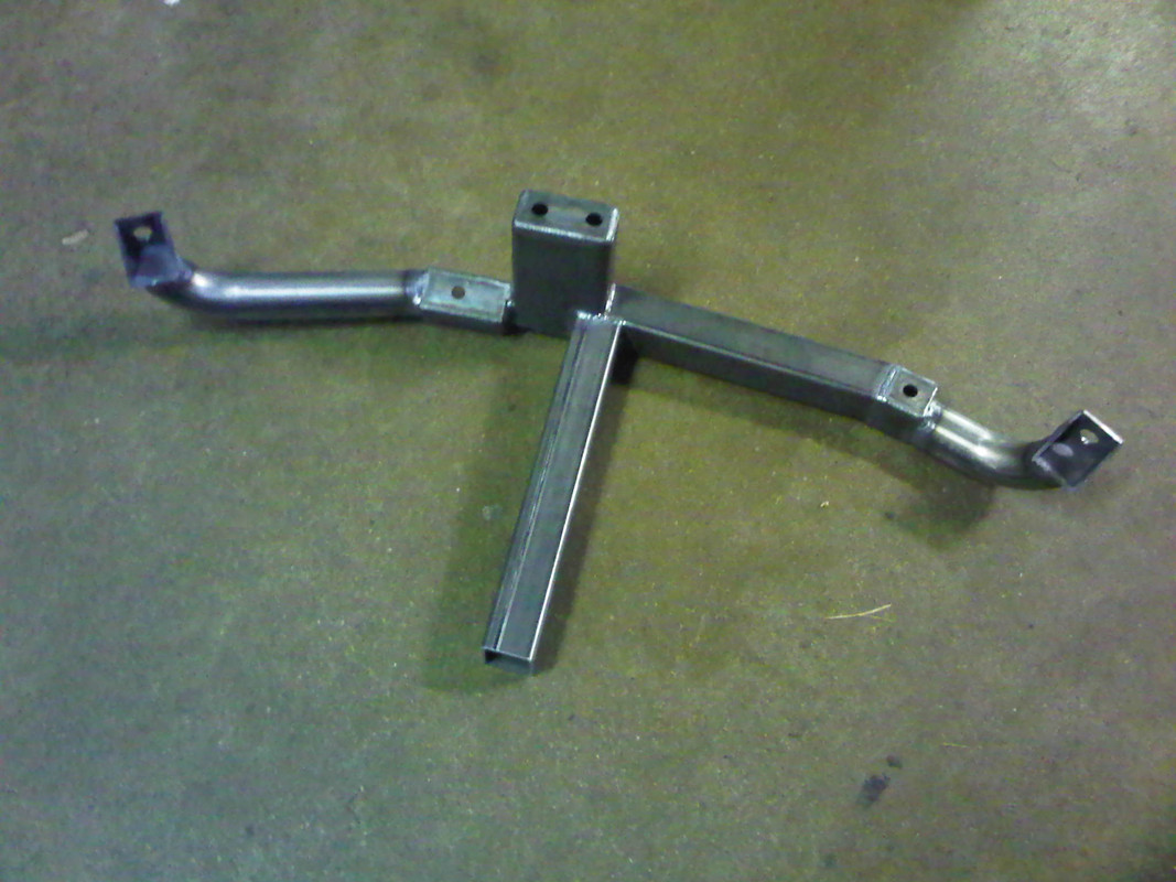
I adjusted my headlamp housing support system
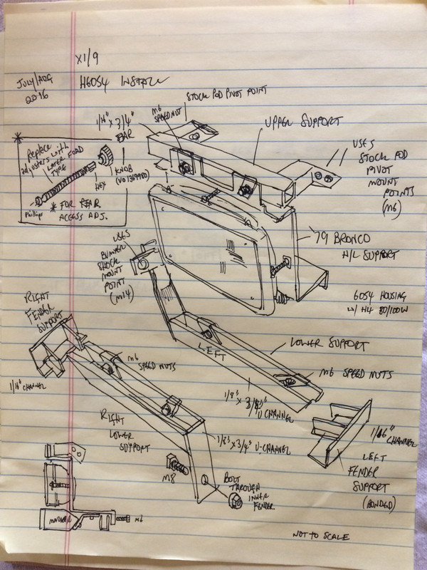
to offset the entire assembly about an inch rearward, so that it will sit with a slight recess at the outer lower corner, the shallowest point.
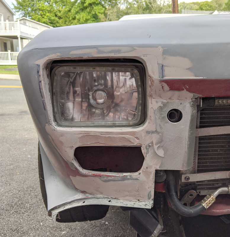
There will be filler panels on all four sides to create the 'bucket'
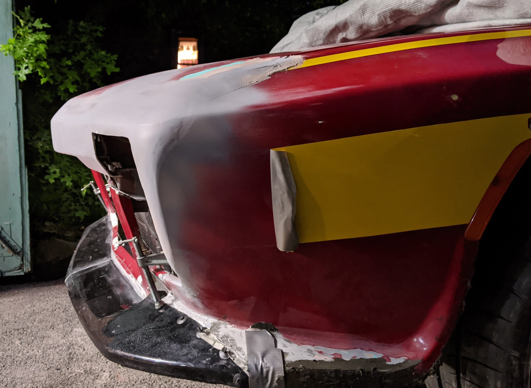
Lower ones have been added here, along with tie plates to merge the fender skirt wrap below the marker lamp aperture in the the vertical grille surround.

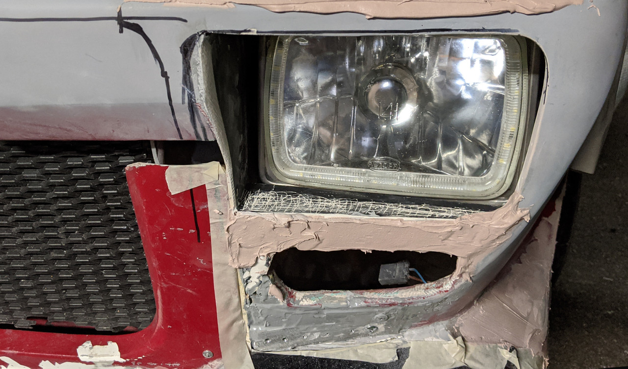
I also need to reshape the headlamp cover areas, hence the additional bondo on top
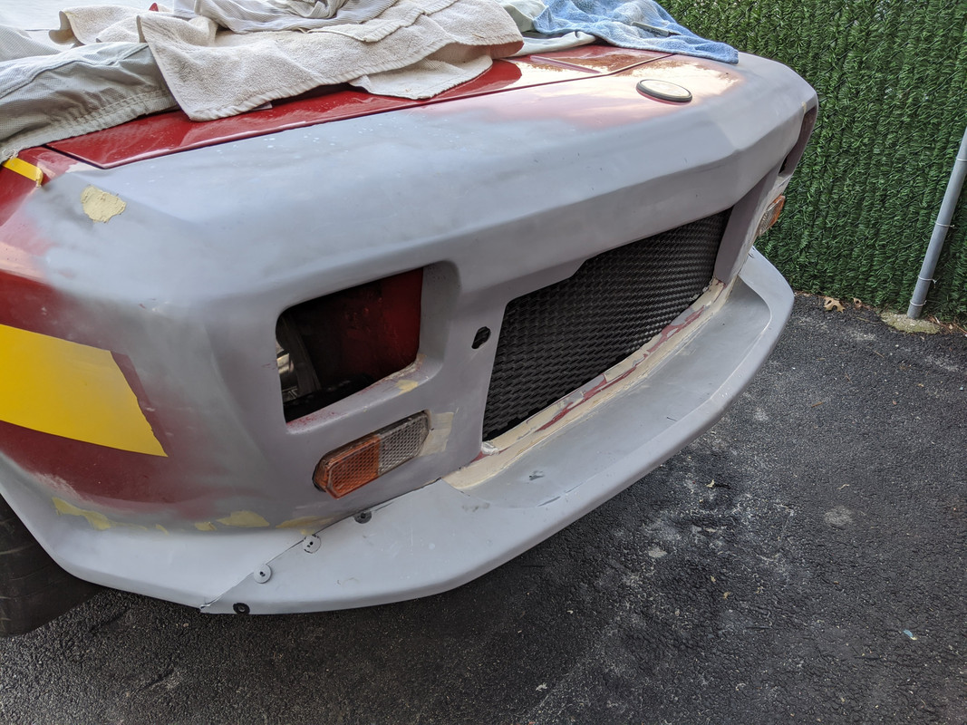
Overall, I think the simplified form will look good.
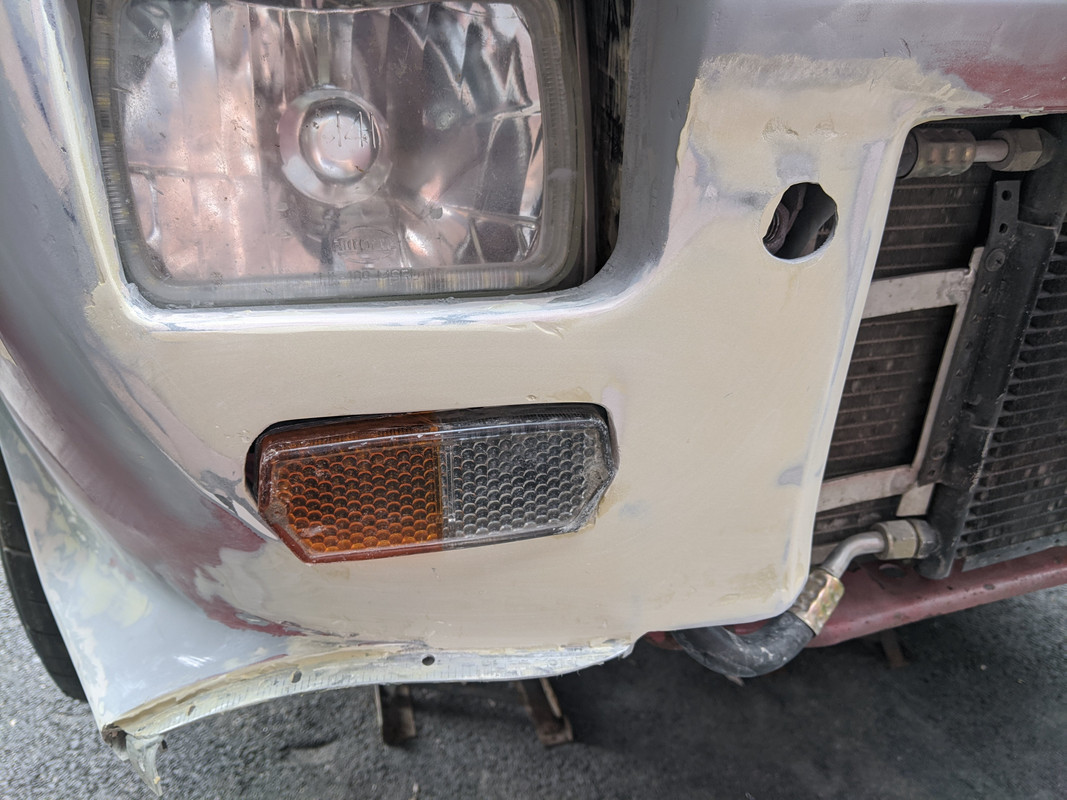
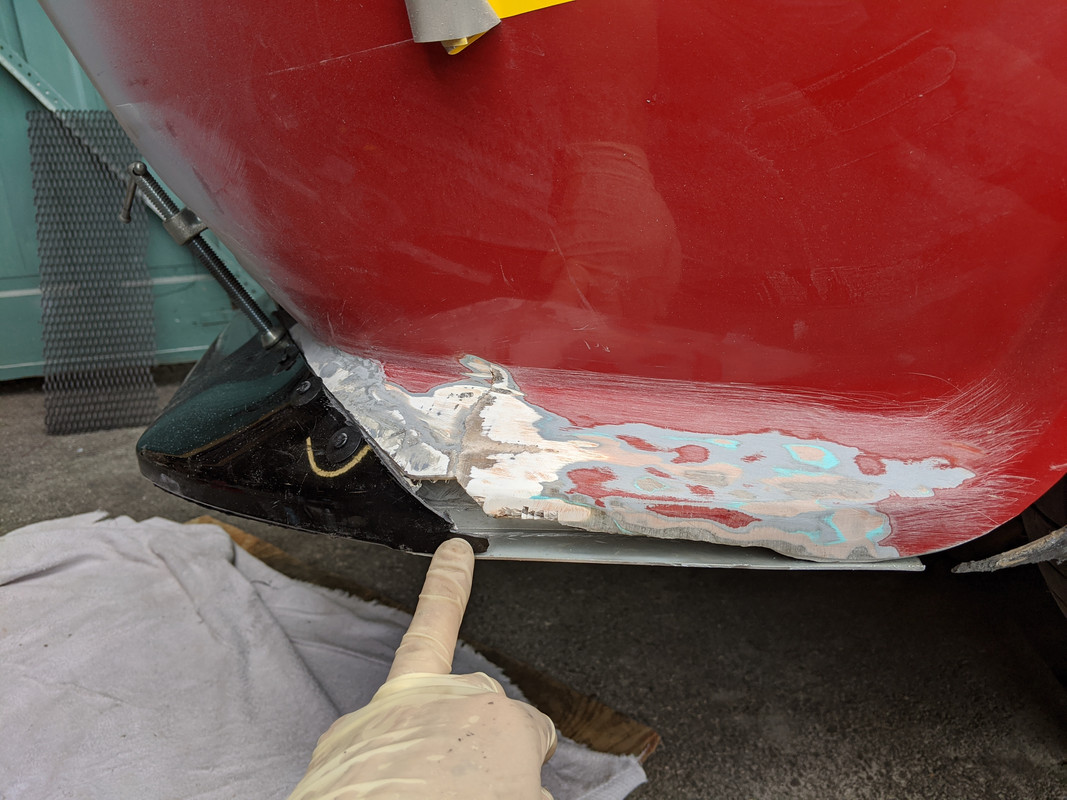
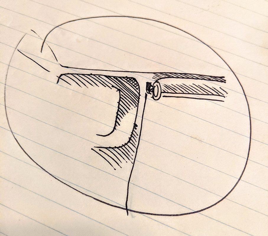
Original modified fibreglass panel work back in 2016. Plan is eliminating all those hard corners around the headlamps & markers
Working on getting that inner radius - hopefully without cutting further inboard - that will make attaching the (removable) spoiler & grille surround more difficult. I think I will be able to create enough of a visual taper & contour to the 'bucket' with some addtional fibreglass & bondo work. Just time consuming getting L & R evenly shaped, since this is all eyeballed. I did make small contour guide plates to test general conformity, but it still comes down to does it look 'right'.
-
2
-
-
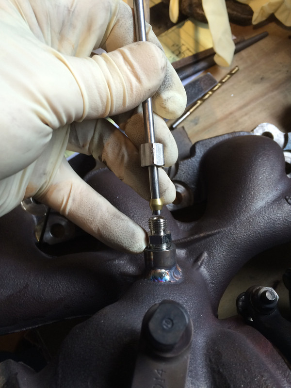
That is truly a thing of beauty!!!!
.... is the breather port designed to take the factory press-in brass tube & filter?
-
1
-
-
Nice work! Looking really good so far.
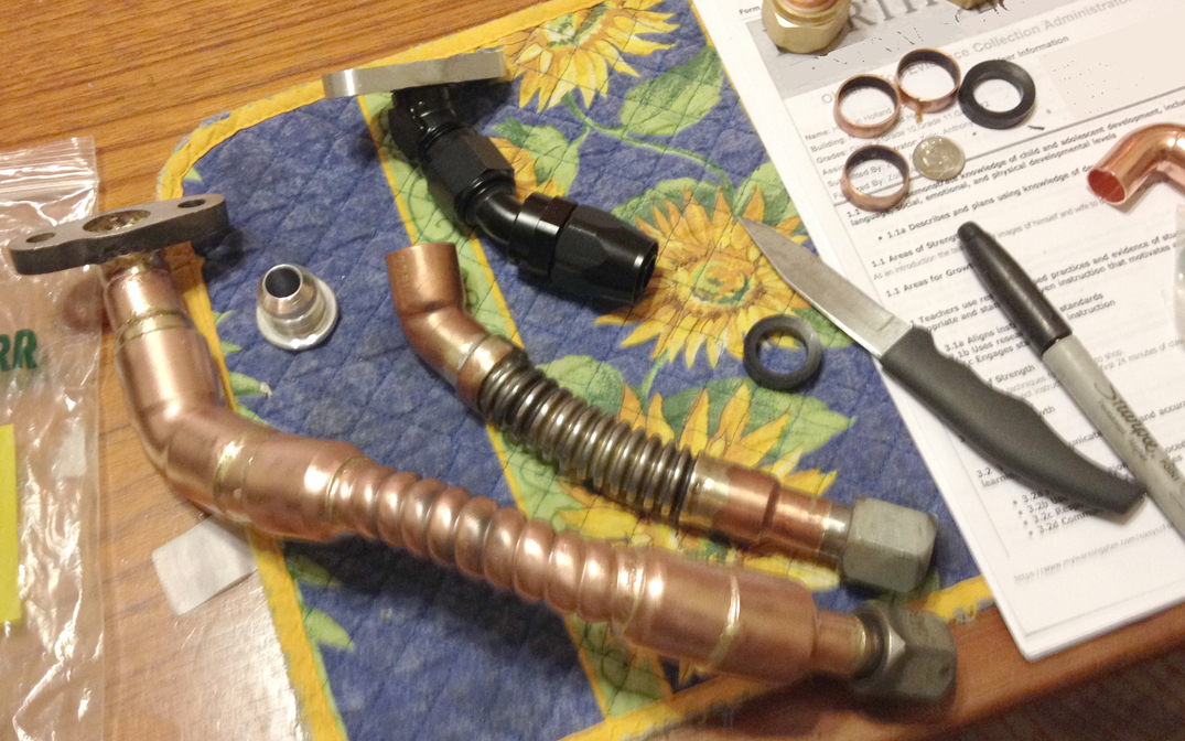
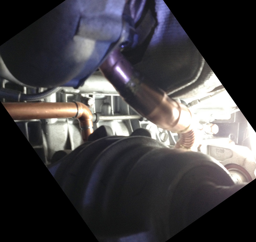
I had many issues with turbo drainage/back flow with the larger frame turbo - the proximity to the AG really screws with drain flow - largely because it is typically aerated if you are running over stock RPM limits & the standard drain ID is way to small when you have to make a hard angle right at the flange. I made several with AN fittings, and they are just too bulky, in the end I made copper line, that worked great but only lasted a year or so. I also used an RNC-prepped block, so at some point I switched to the later drain port, and used the stock port as another vent. A large bore (over 5/8) , rigid pipe drain design would be ideal. Having the 'reservoir' helped allow for the aeration, vs. straight bore.
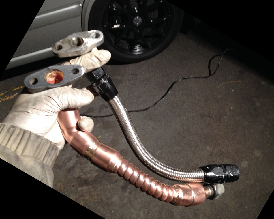
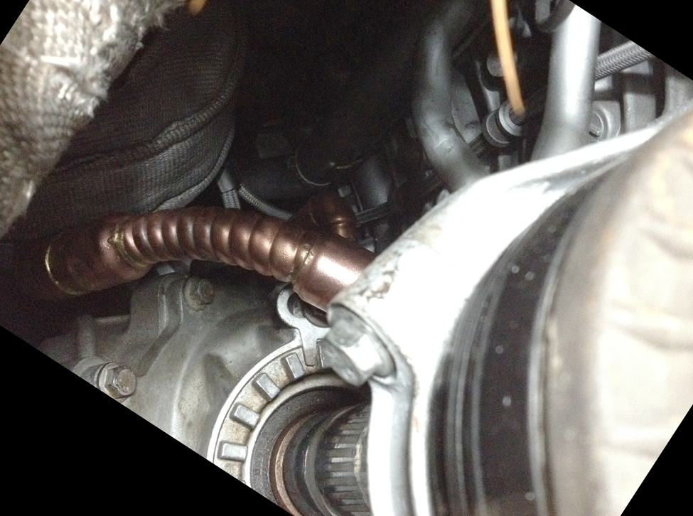
with the DP, you definitely want the prop shaft & flange in place before you fabricate, since the DP has to tuck around it - this is the basic shape that worked for me through several iterations. I should strongle recommend adding a flex coupler up there, given the amount of torque you are placing on the drivetrain. With PB account gone, I lost most of my pics. Don't have any that show the flow around the prop shaft. The front CV will cook if you don't have a good air gap. I tried heat wrap on one version -didn't work out for me becuase I had the hood vent, so water was always soaking the header/DP & compromising the setup
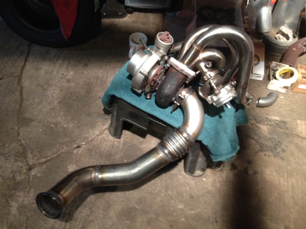
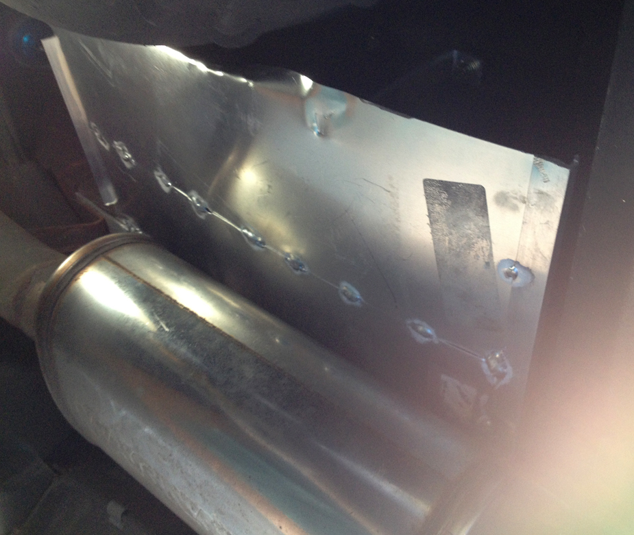
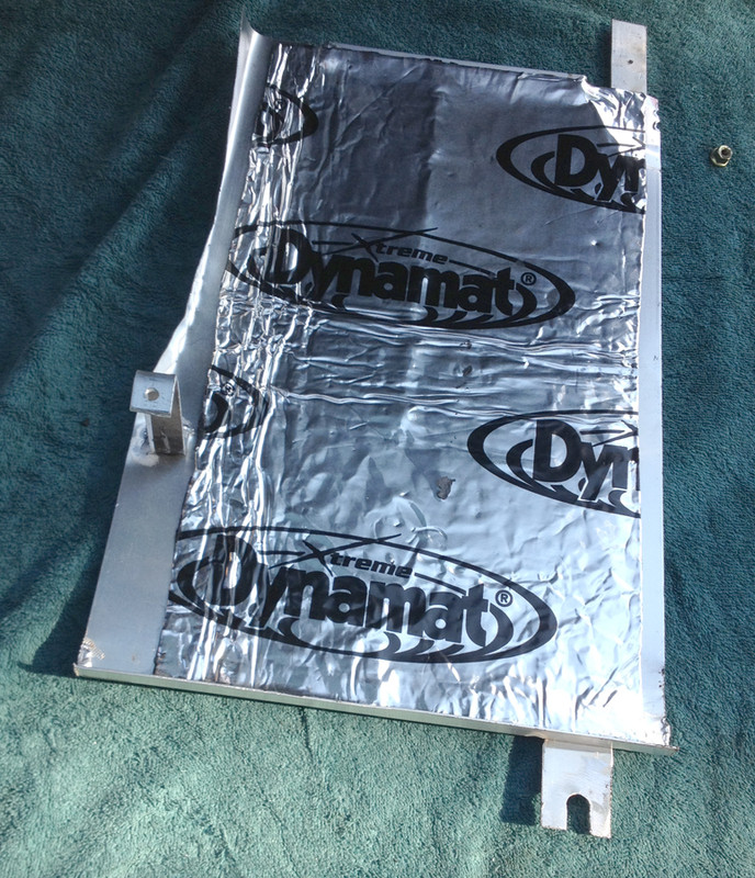
I also had to add a heat shield for the surge tank on mine, with the dual muffler setup the right muffler was too close to the tank
-
2
-
-
Sorry - I wasn't implying it was in any way a better or stronger setup compared to your needs. Just a cool mod.
Personally, I don't like the Haldex given the shitty power distribution Volvo/VW etc., set it up for, with no provision for close to 50/50 spilt. With my old wagon & VC I got 50/50 as soon as I got around 350AWHP. I think the weak link of the VC is the freewheel mechanism, at least in my experience, that was always the failure point. I guess if the VC leaks, then the loss of the silicone-based fluid would kill it. Perhaps it will overheat & cook when put through your power levels though. Time will tell on that one.
Back in the 80's I did snap a ring gear (w/Volvo LSD) in two in my old 245TI w/a 50 shot - so it is possible that will fail for you before the housing ever would - I guess that depends on how you can preload the rear to prevent that slack on launch that also exploded my angle drive years ago...
I am going to be using the VnDeVeer Haldex Controller with VW Haldex on my C30. With his controller, I can tailor the torque split anyway I want. We'll see how it goes, all I know is the setup with the Gen3 controller is still less than stellar, too much front spin. With my wagon, there was no drama, just go - I want that in the C30
-
1
-
-
13 hours ago, quiksilver said:
Hussein, where'd you find this? I'd love to read more about it.
9 hours ago, aziz said:u have a link?
is this a xc90 or a p1/p3 one?
tia!
Unfortunately that's all I have. Those pics came from Van Der Veer Haldex Controller. One of his customers did that & uses his controller to govern it's operation. I'll message him & see if I can get more background. I have no idea what the diff is from, could be VW for all I know, the Haldex has to be to work with VanDerVeer Controller.
-
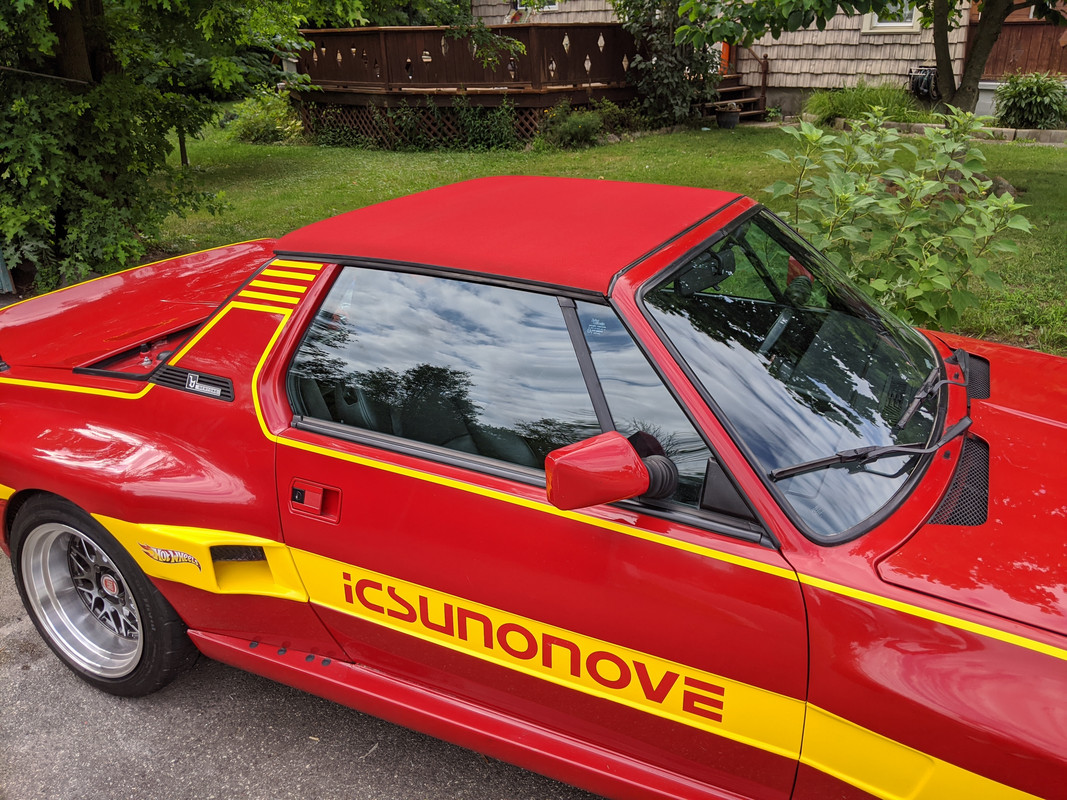
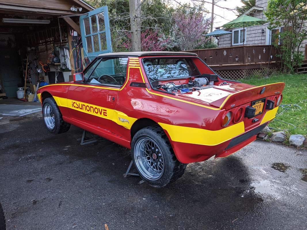
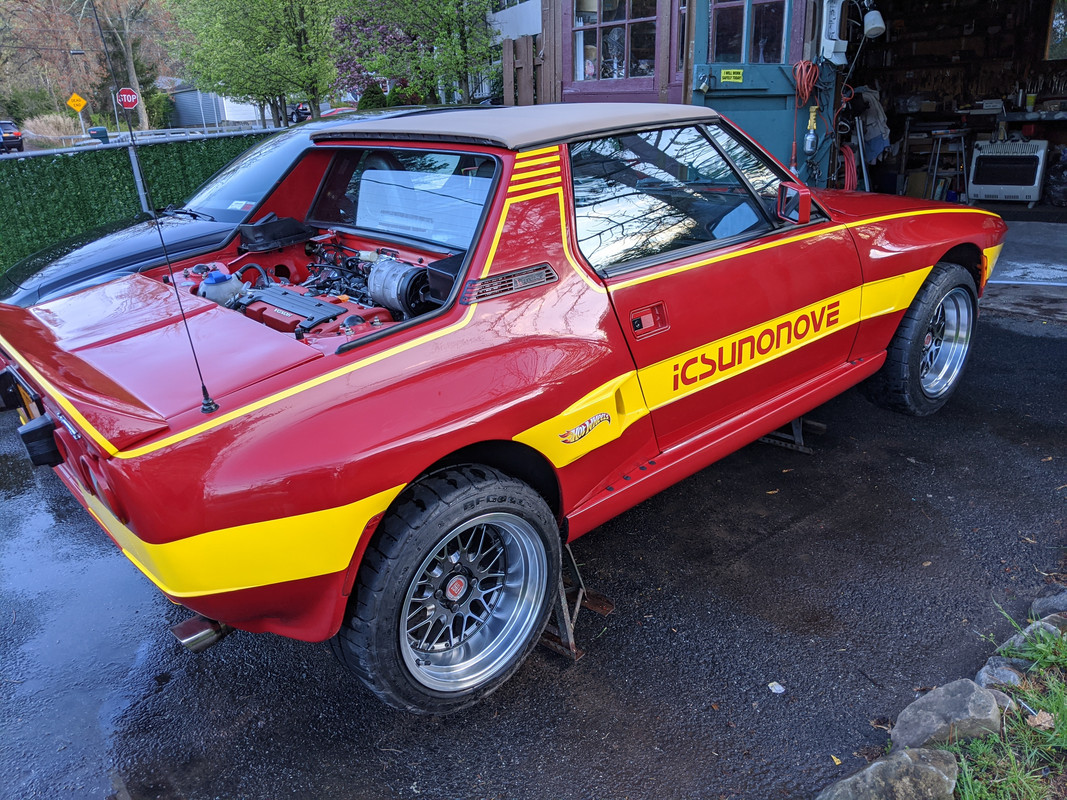
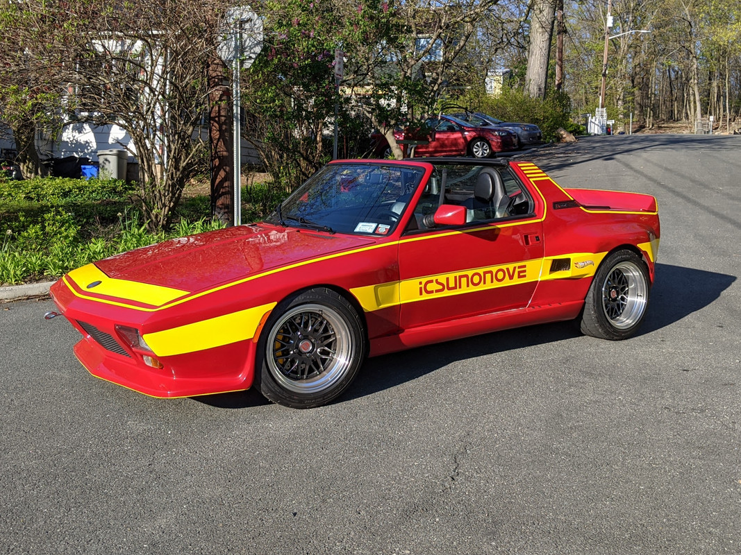
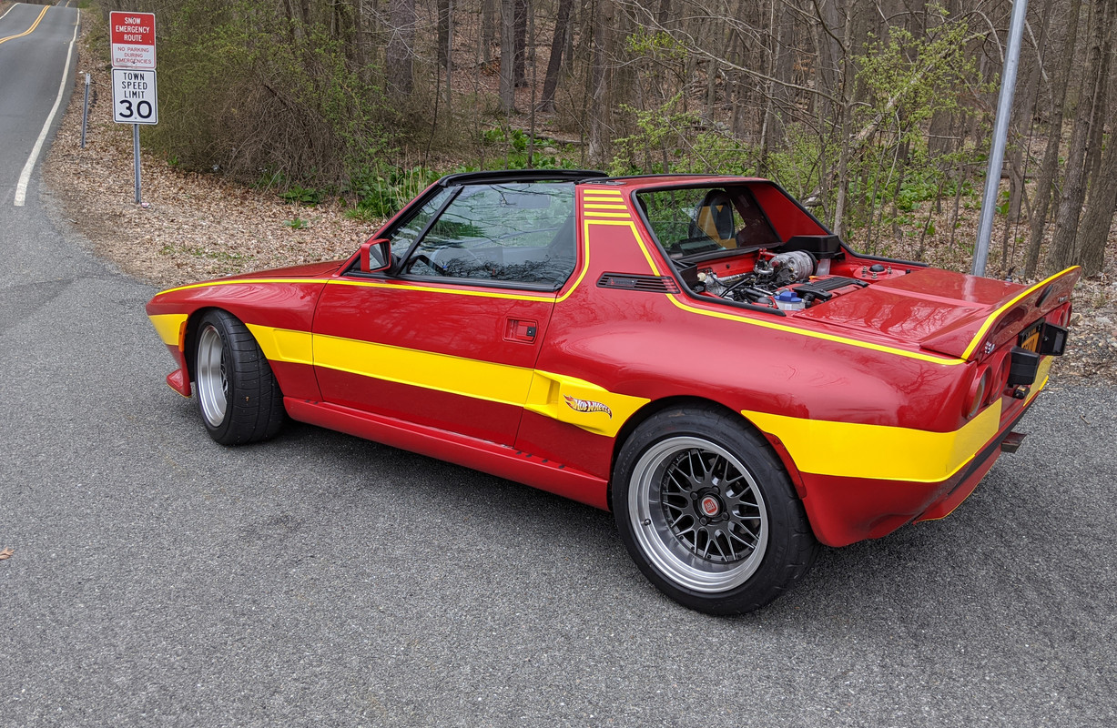
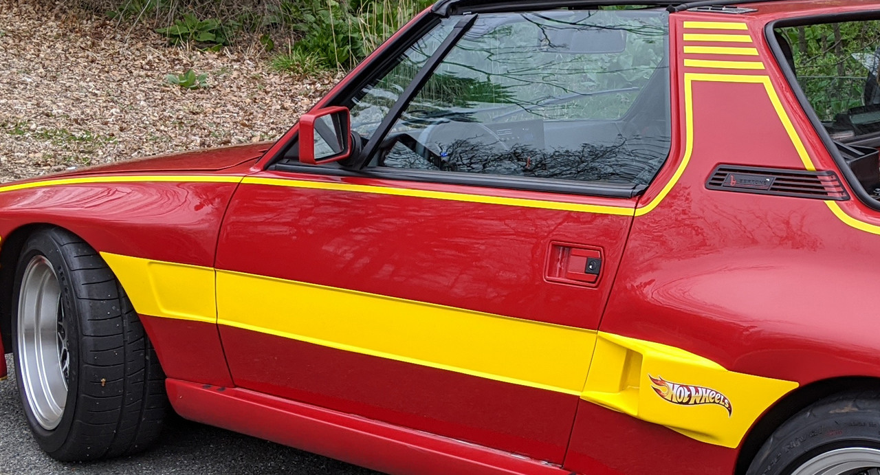
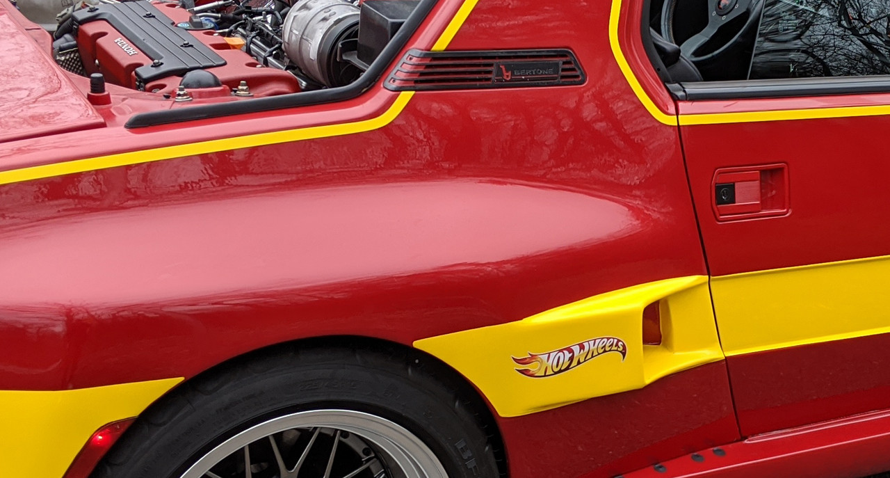
3M vinyl lettering finally came in yesterday , and it was a sunny warm day (for a change), so I got the lettering installed.
Went easier than I was expecting - has a nice firm transfer sheet that keeps the lettering positioned
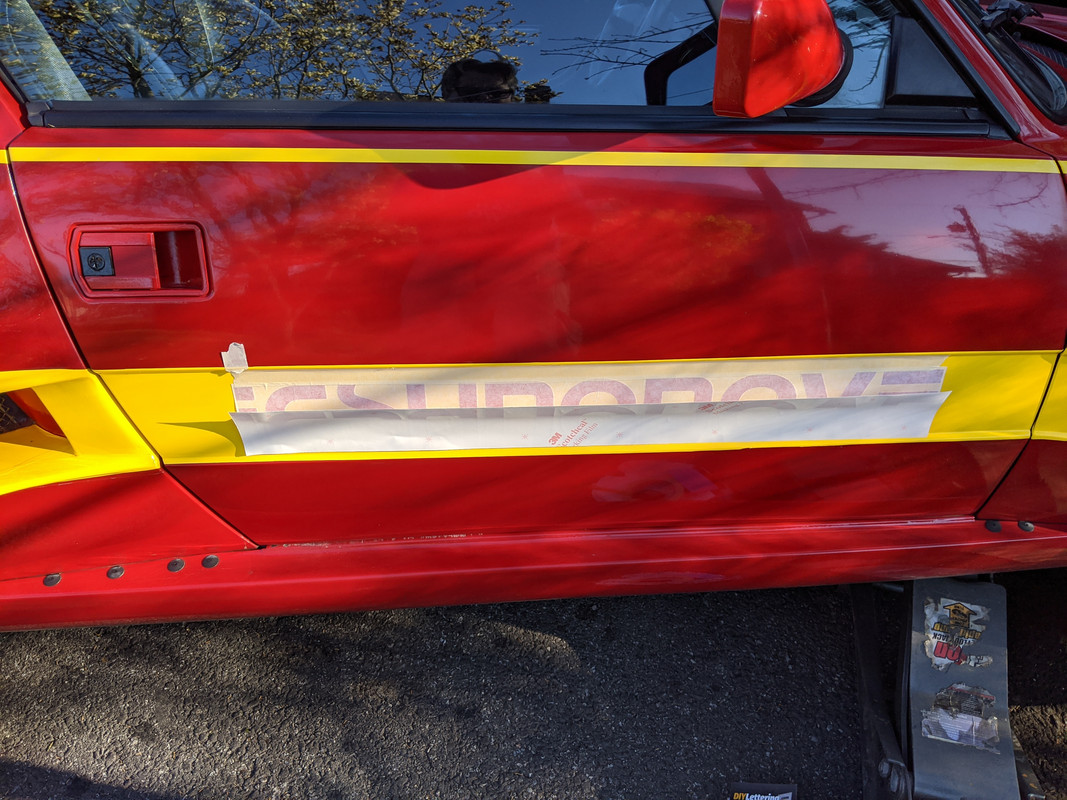
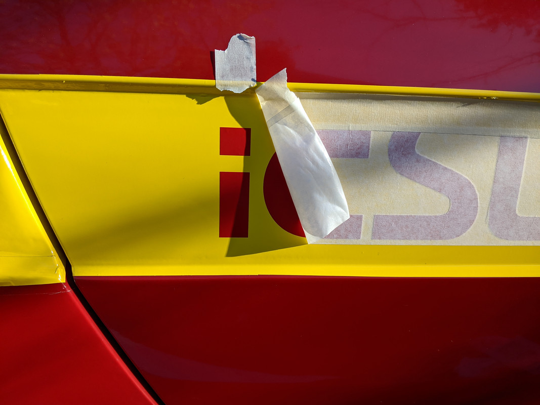
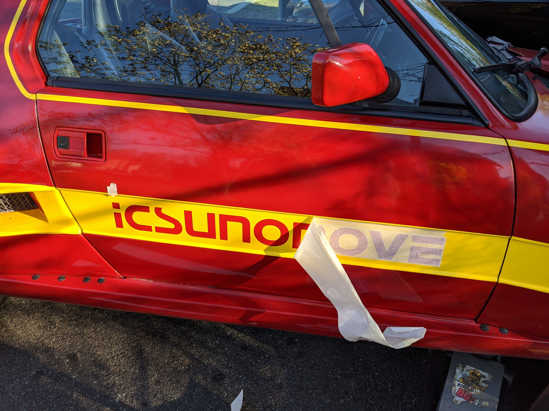
3M 'Dark Red' scotchcal film. Matches the Volvo red reasonably well
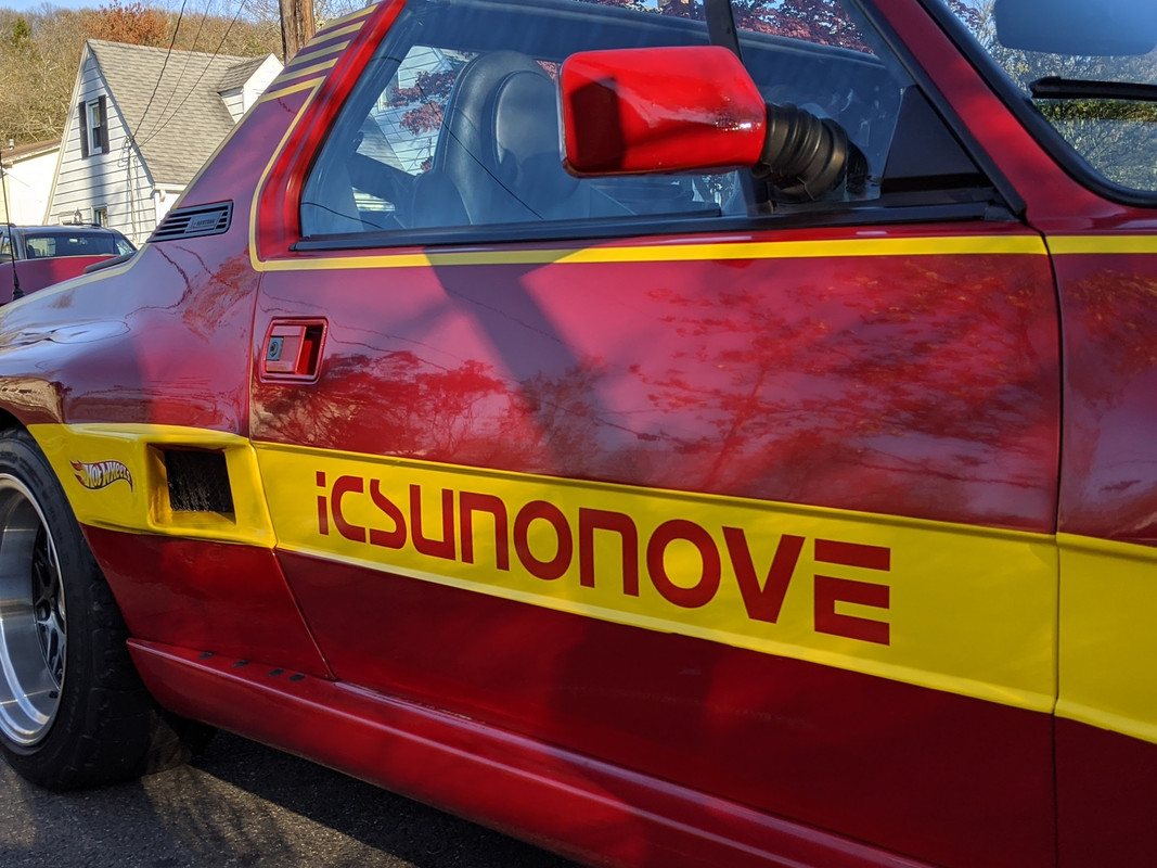
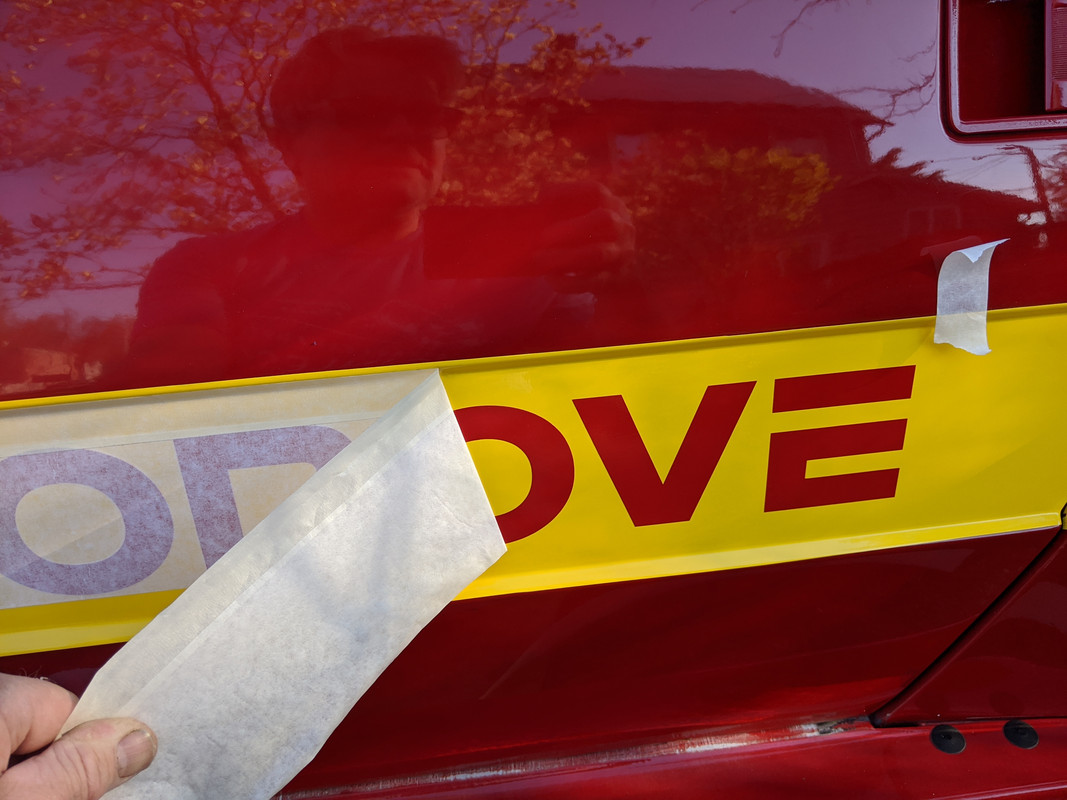
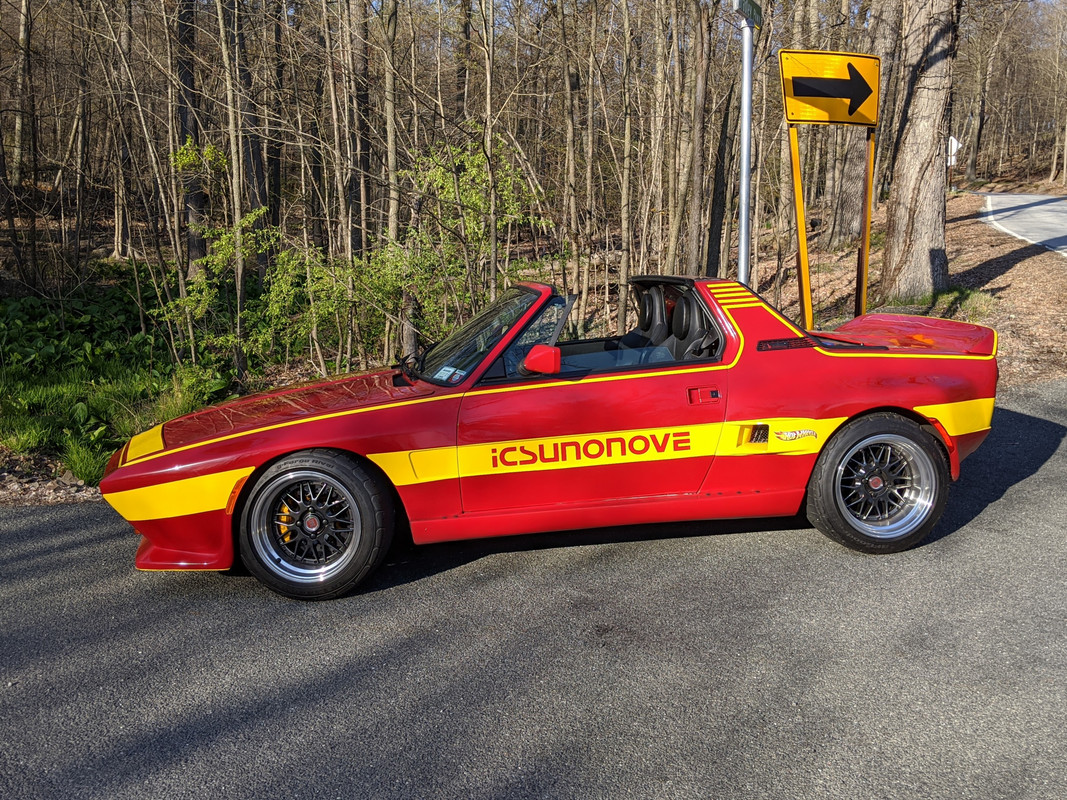

I'm happy
-
4
-
-
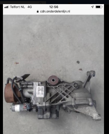
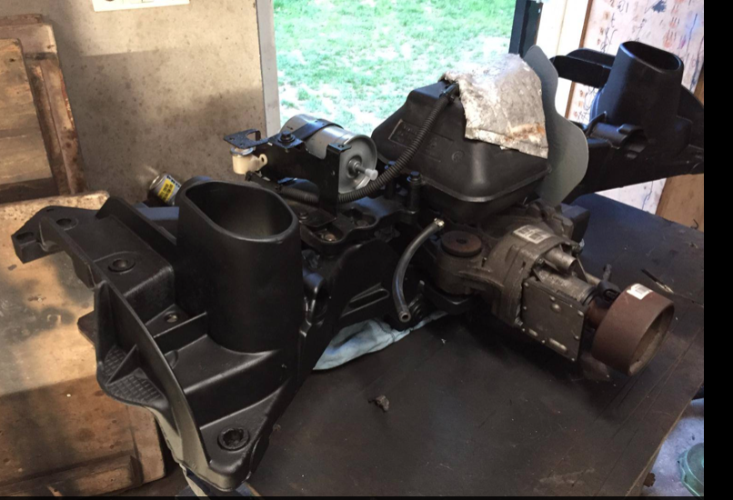
I'll just leave these here - modified Gen5 Haldex dropped into P80 in Europe - using VW Haldex controller
-
2
-
-
LOL - when I first went through the vid I had the sound off - and I was wondering what the heck the fake bearing were for, since obviously end float on the pumpkin is way off that way
-
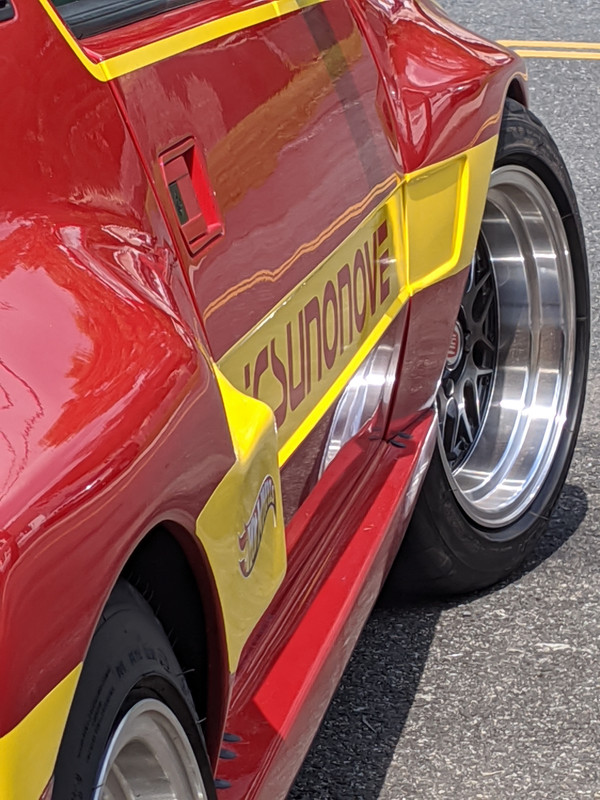
Waiting for color samples for the "icsunonove" lettering. Ordered another sticker I feel is appropriate now:
-
4
-
1998 V70 Xc From The Beginning... to the End
in Show Room
Posted
My district is doing Hybrid. The rest of the county is remote only. Just faculty through next Friday, Kids come in the following week. 6 cohorts, about 800 per day. We will have around 4200 kids 9-12, - 20% opted for remote only (around 4800 total student pop).