

lookforjoe
-
Posts
13,471 -
Joined
-
Last visited
-
Days Won
92
Content Type
Profiles
Forums
Gallery
Blogs
Downloads
Events
Store
Bug Tracker
Posts posted by lookforjoe
-
-
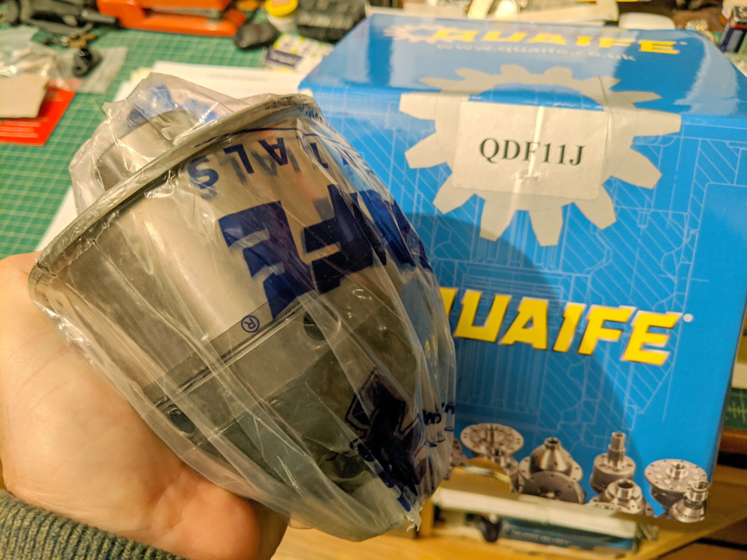
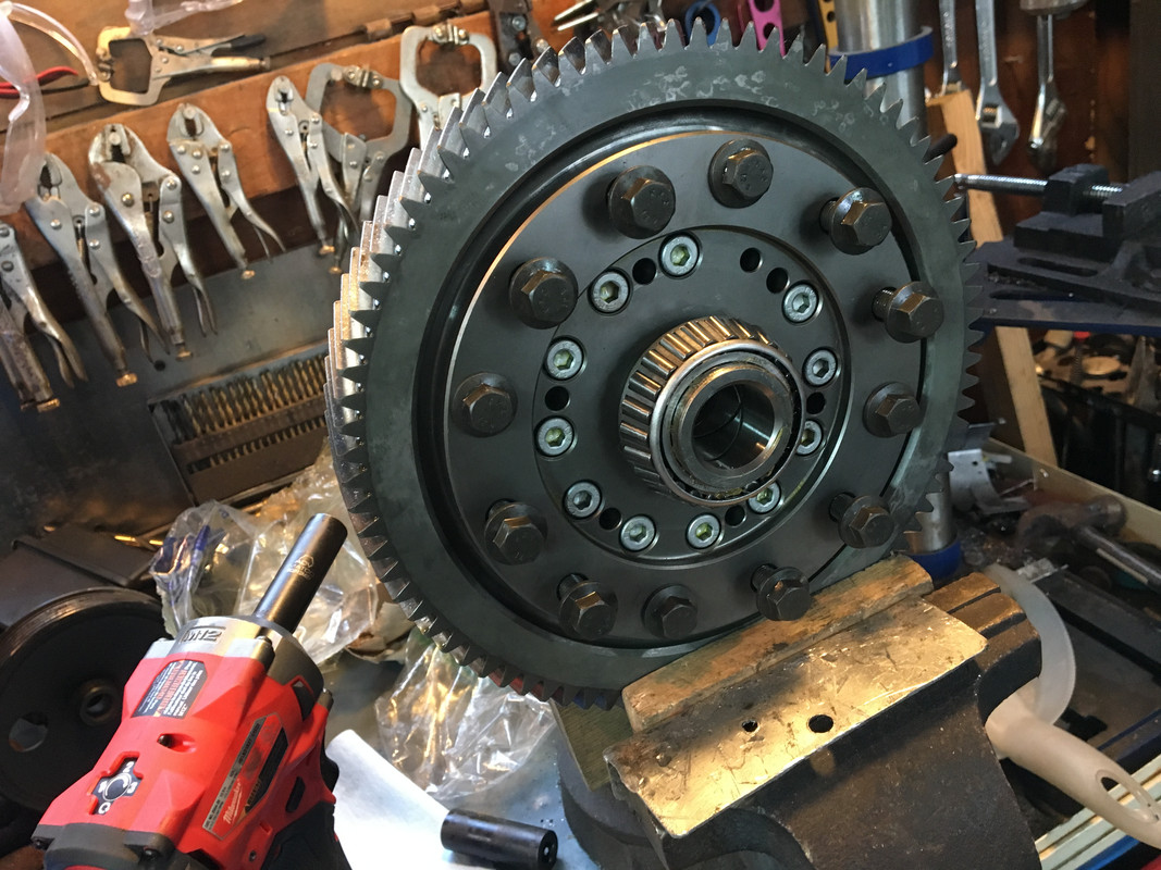
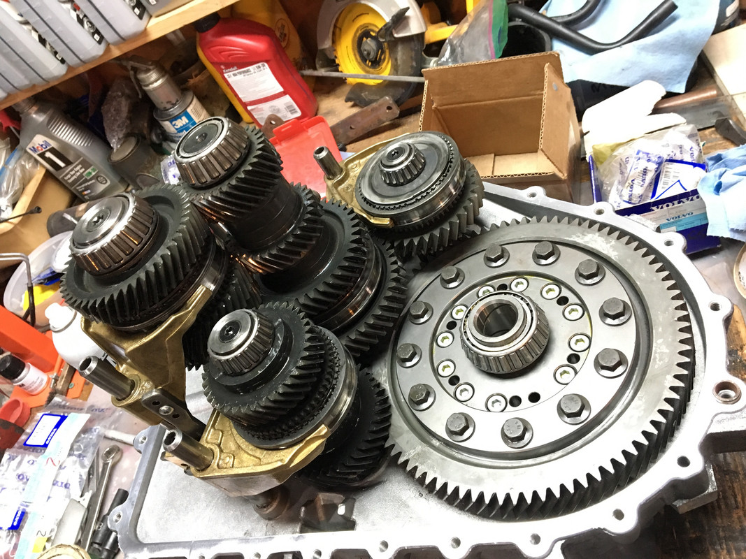
AWD Ring gear is now transferred & welded to the new rear Quaife 11J LSD. $250 later it's done. Now I have to install the new bearings (32008X/Q) and check the backlash.
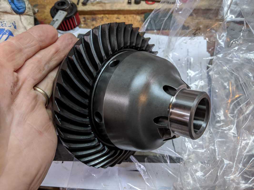
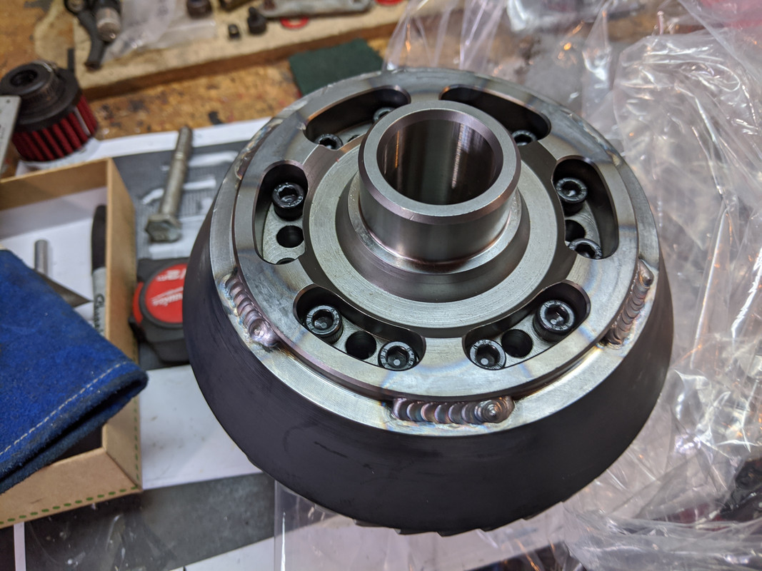
He said it was a royal pita to essentially machine the old diff out of the ring gear, the welds were deep
-
23 hours ago, gmsgltr said:
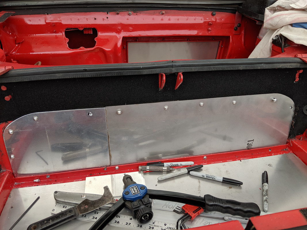
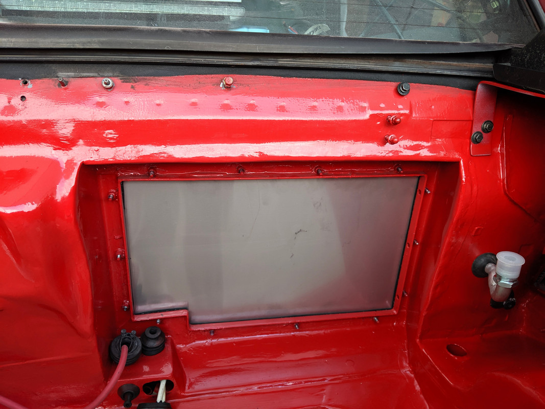
What type of bumper insert goes in that void? It will likely conceal it from not being level anyway. Nice work!
There is an aluminum slat panel that covers all that, so yes, one cannot see it once it's covered :)
 3 hours ago, tighe said:
@lookforjoe It’s so nice to see you back in the machine shop making and modifying stuff. The photos of your fabrication skills now account for about 2/3 of my enjoyment of this site...
Thank you - it is enjoyable, making stuff :D
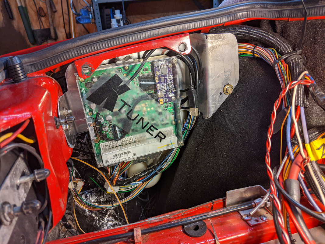
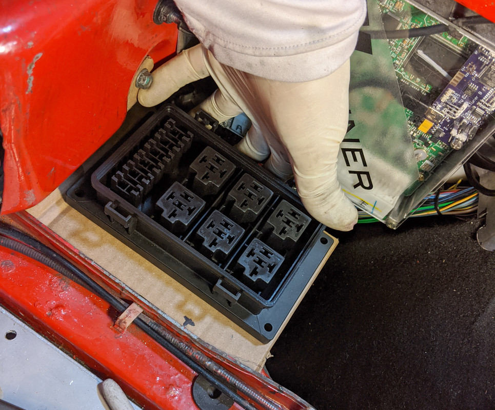
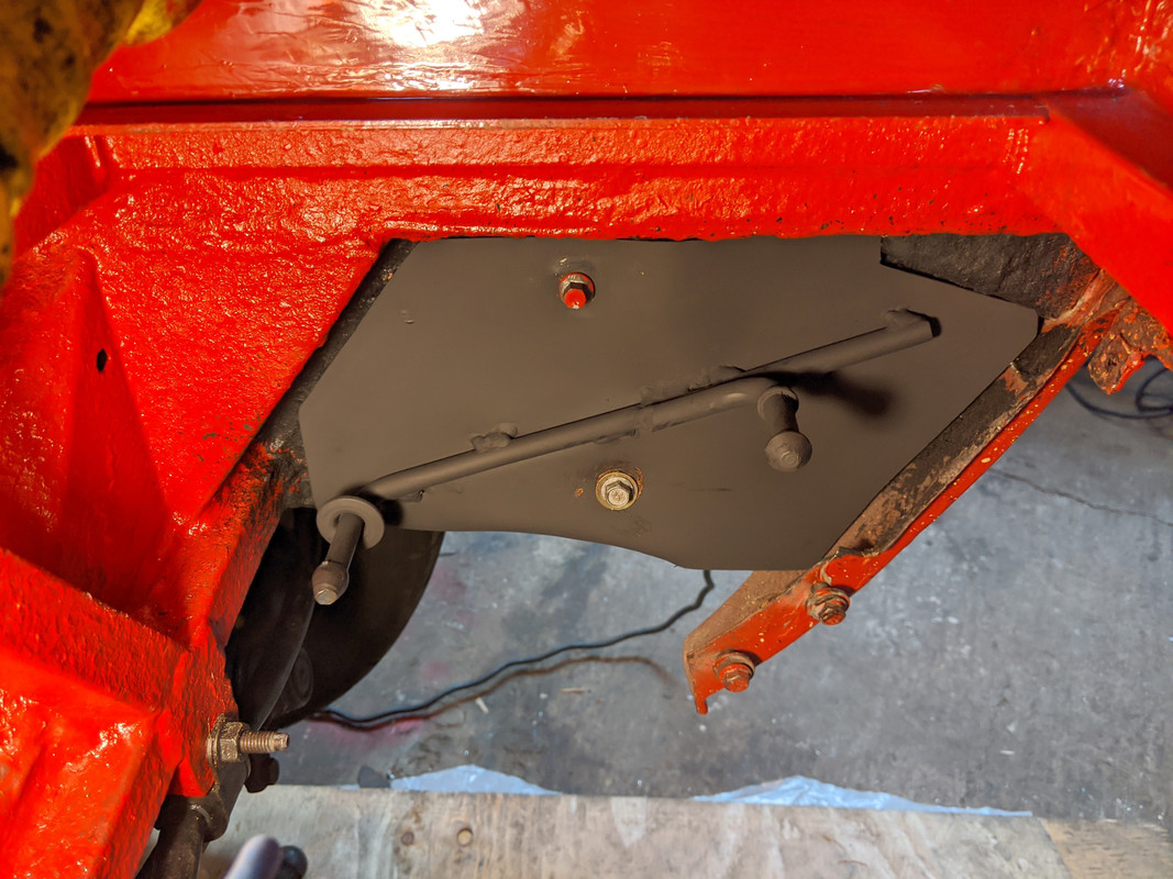
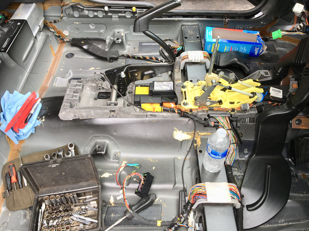
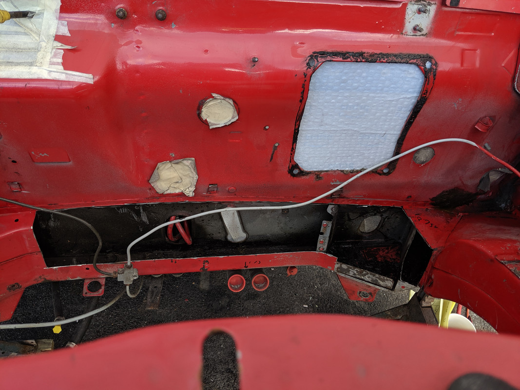
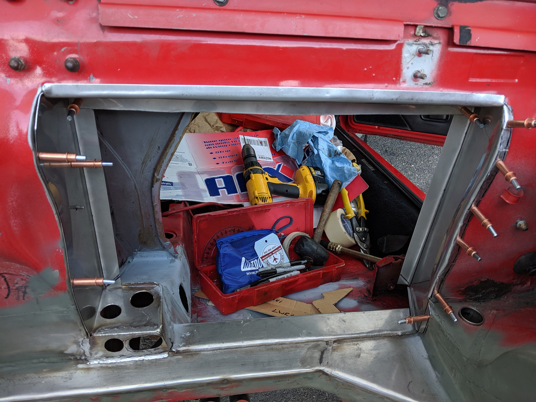
Finally had a breakthough in terms of having a direction for the ECU, bus bars & relay box layout. Slow day at work, so I did some sketching to figure it out. Was thinking along these lines (in the left cavity, vertical strip on the right being the left frame rail):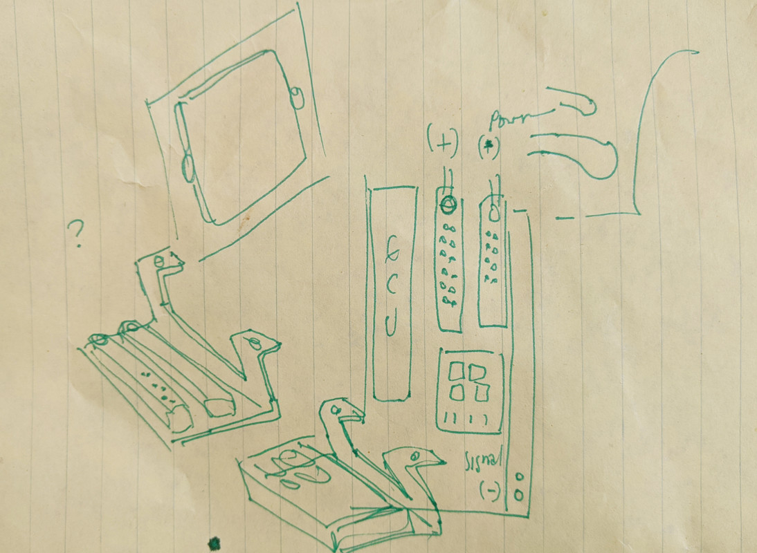 played around with some cardboard, and then made the aluminum version (used the neighborhood watch sign). Recessed to keep the ECU as far in the fender well as possible. Bolted to inner wheel arch and taillamp support.
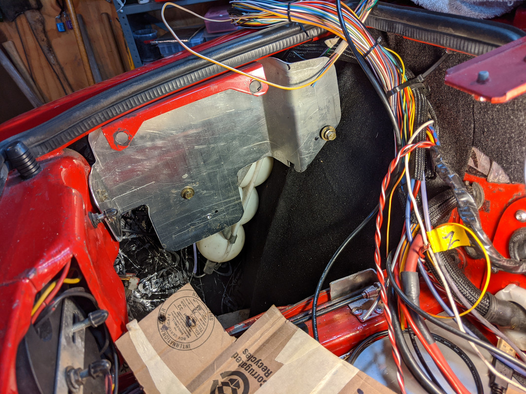
 Then I figured out the support for the relay box, and the bus bars
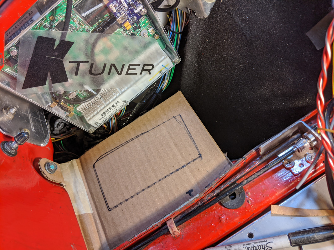
 template:
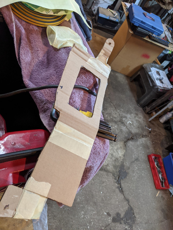 cut & folded, rivnuts to secure the relay box & bus bar. Pos bar will go to the right
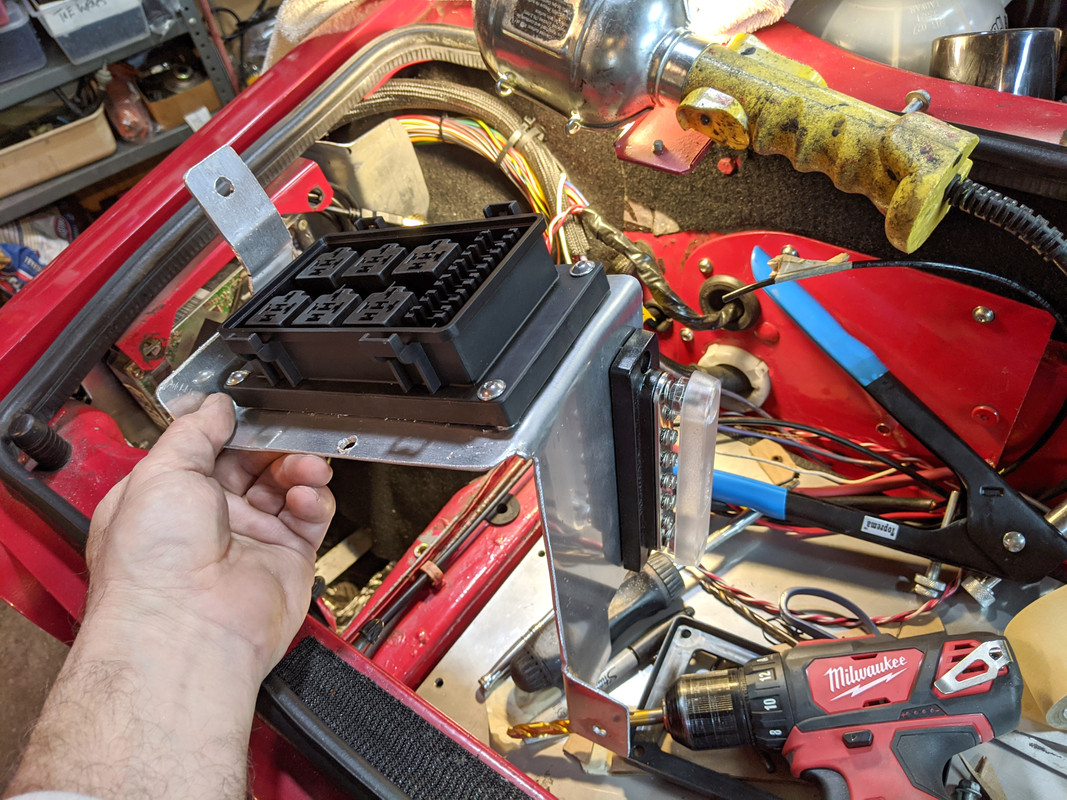 anchor at the base - using the bolt that also secures the exhaust hanger plate
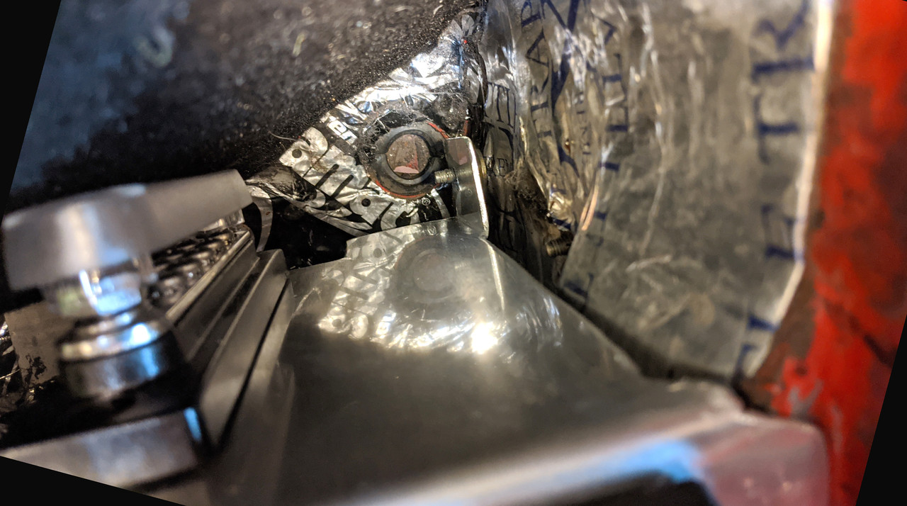 Now I can get on with the actual wiring, once I get back from visiting my daughter & grandchildren in Orlando.
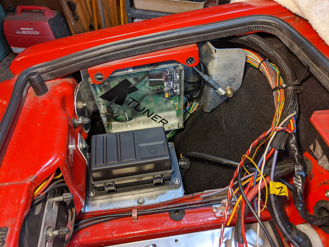
-
 1
1
-
 1
1
-
-
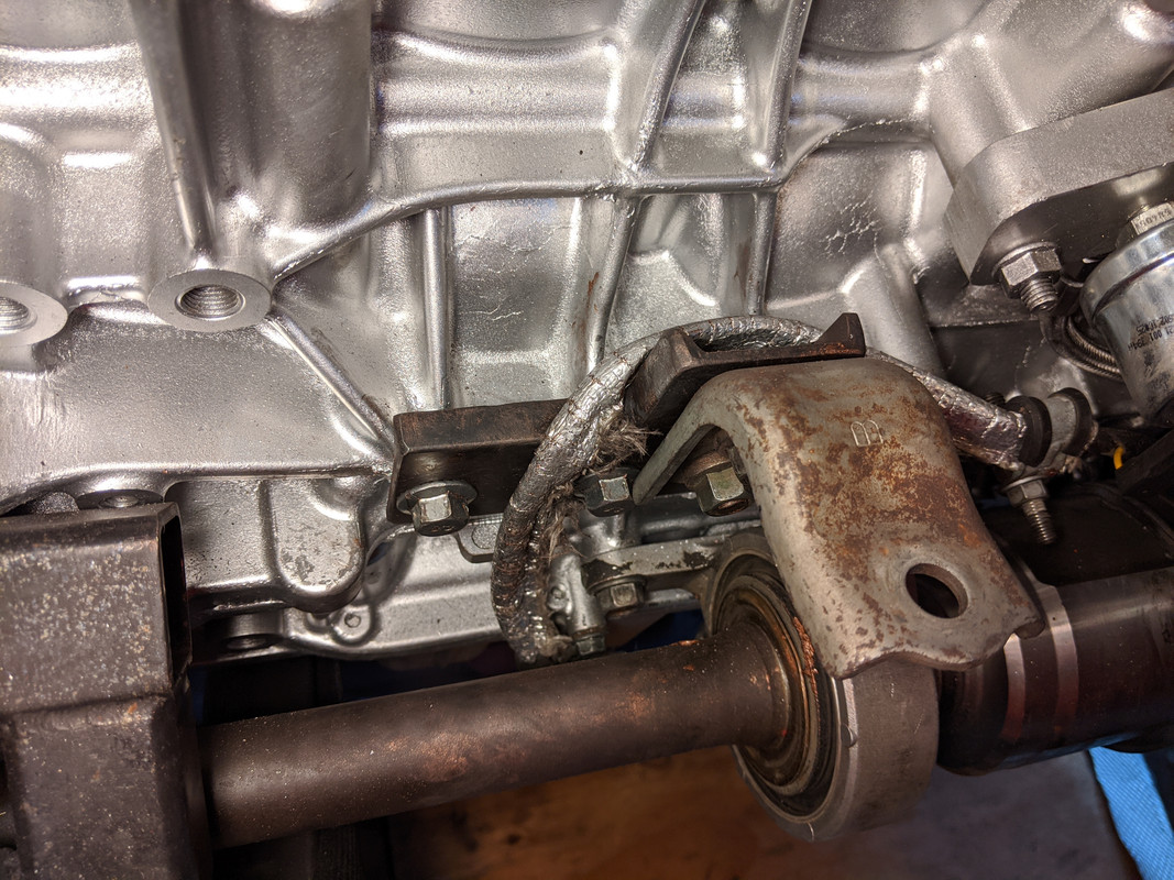
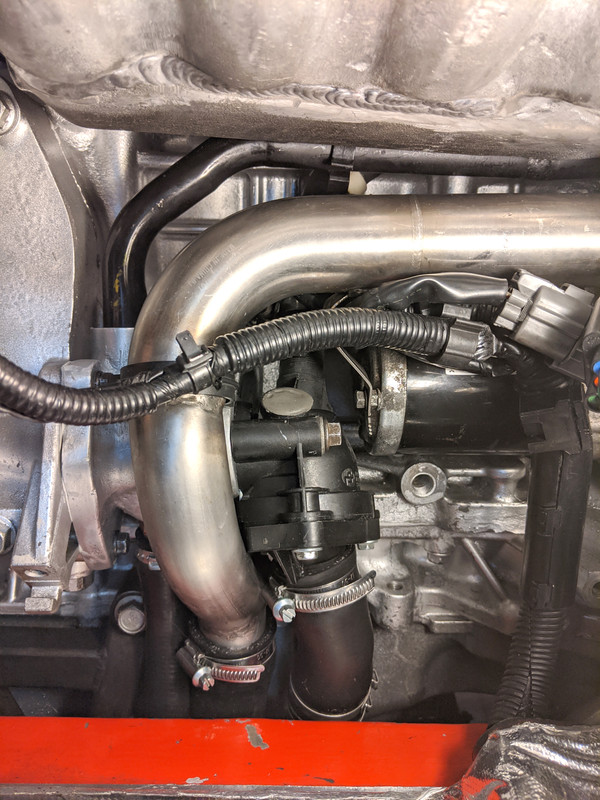
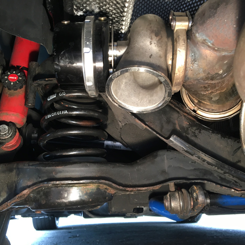
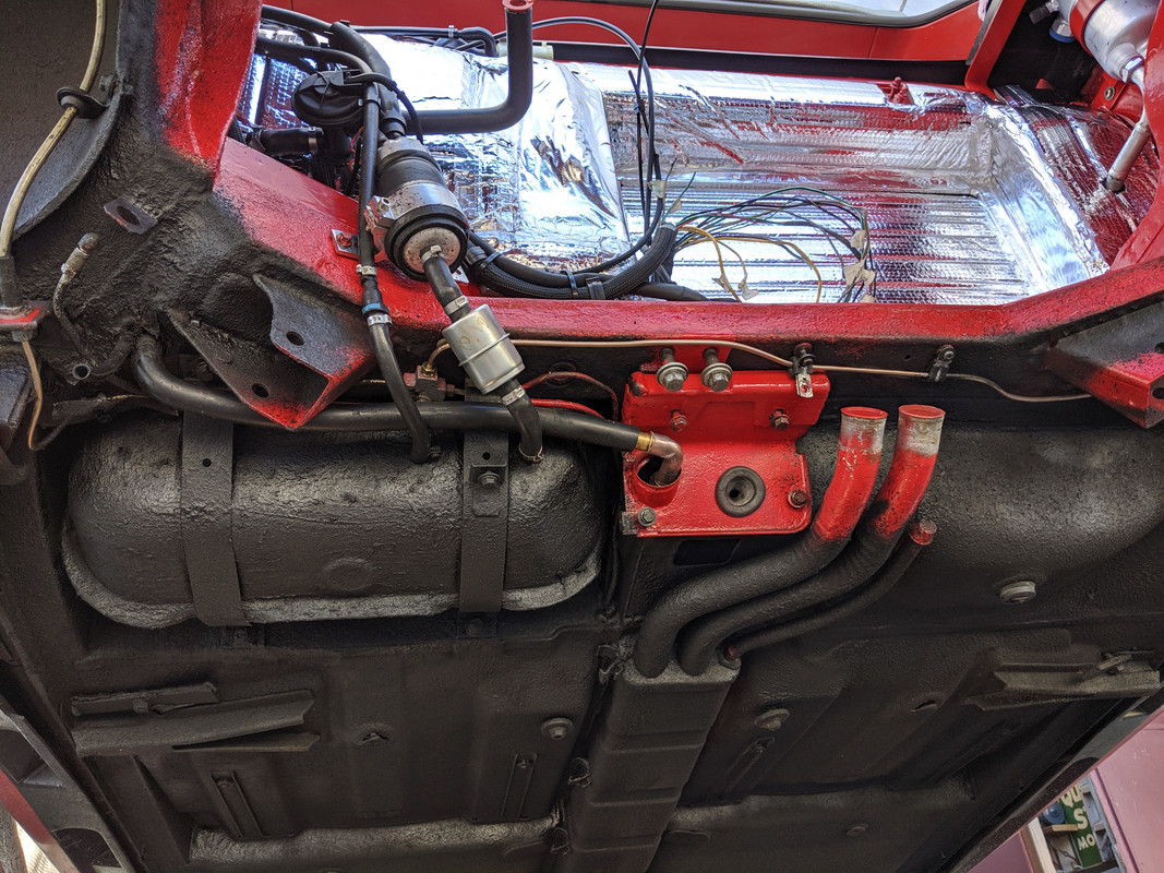
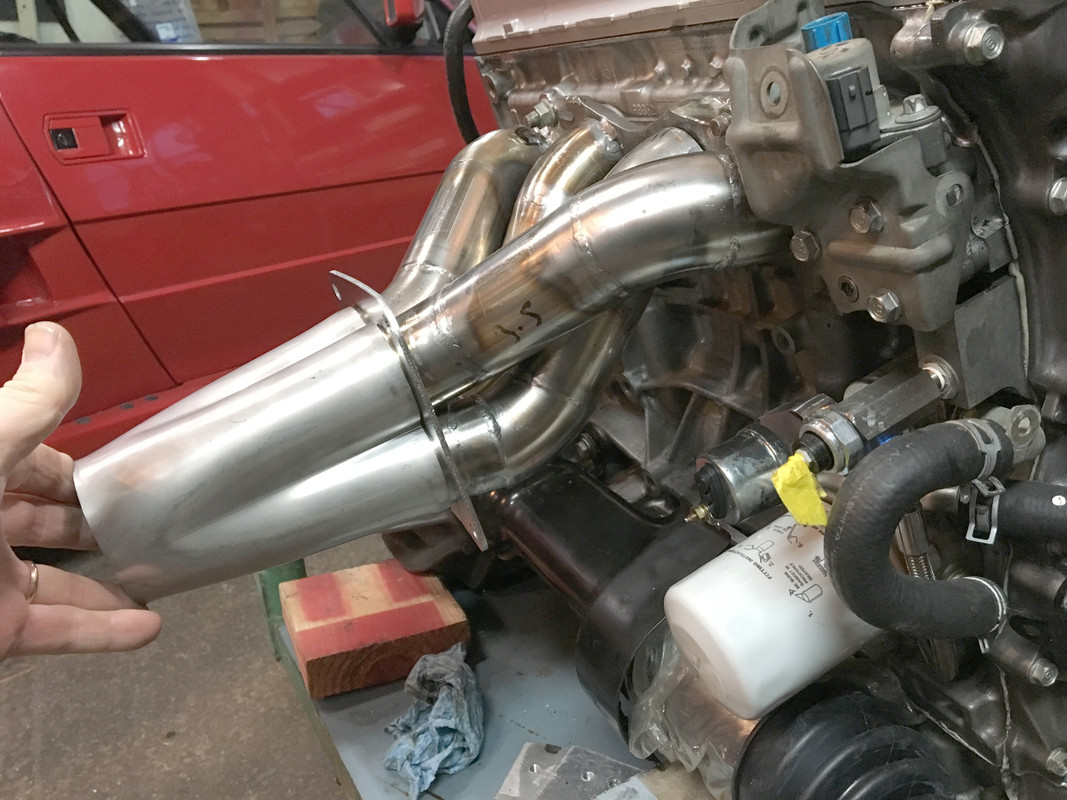
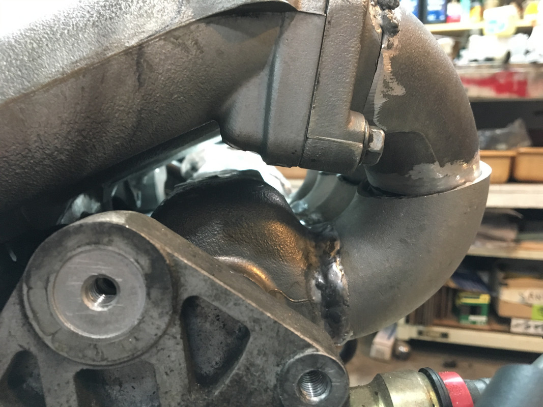
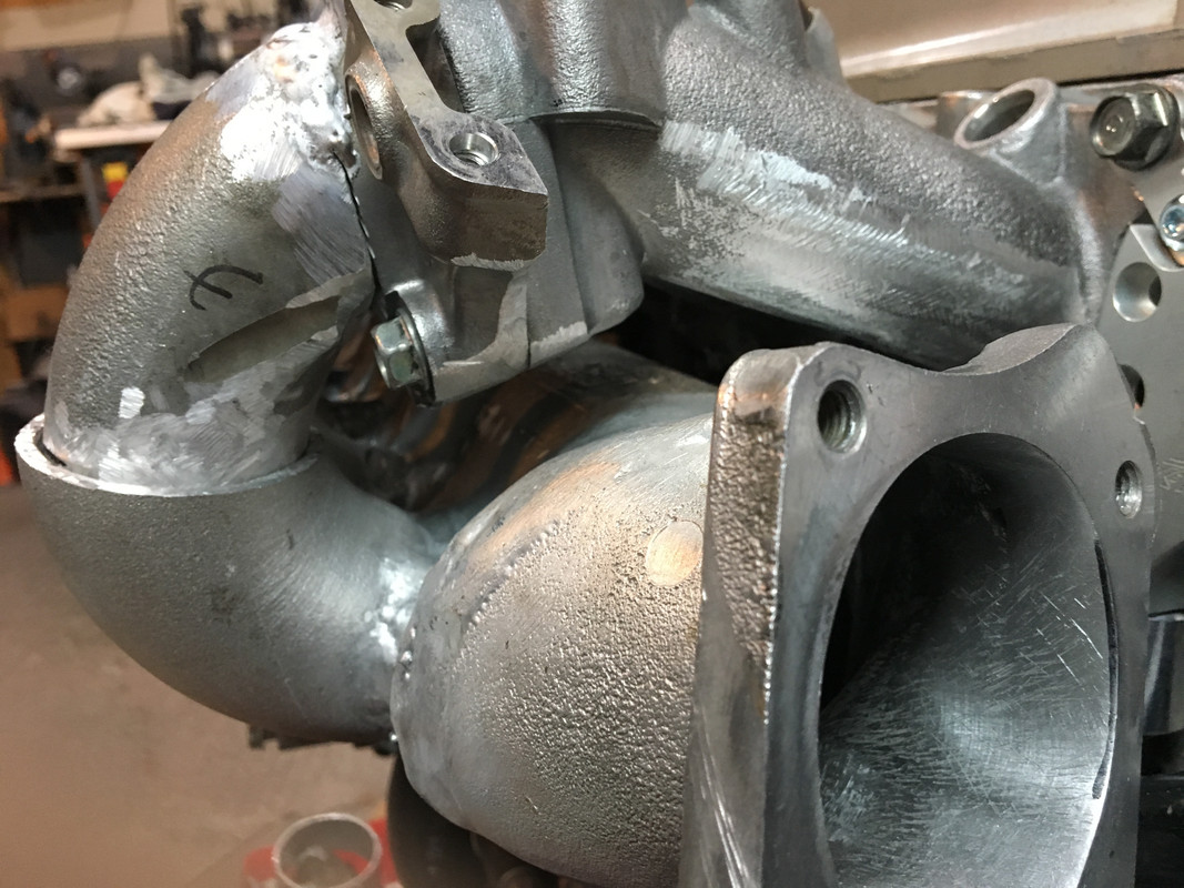
Made a bracket that mounts underneath on the block - wasn't happy with the idea of a side brace. The factory elbow bolts to that, and then a SS tab will be welded to the header collector

 had to add a vertical section for the upper securing bolt of the elbow bracket. Bolts are welded on the backside.
 Honda bracket goes thus, with the header bracket on the other side
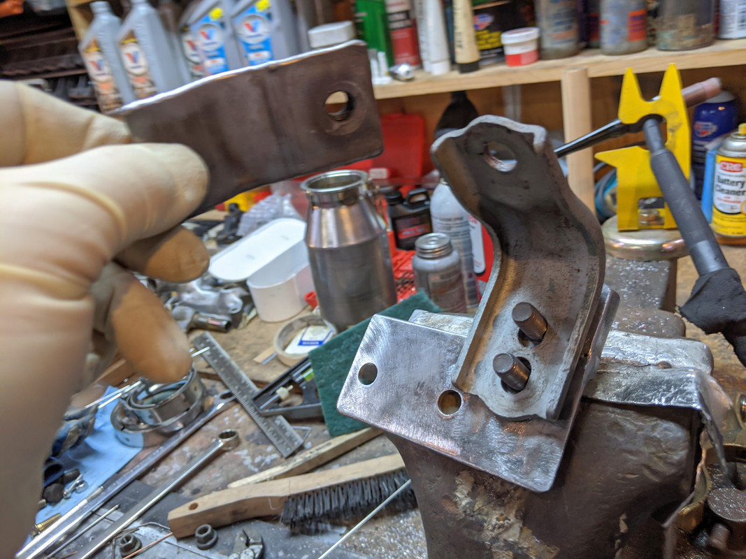 All bolts are easy enough to access, nothing fiddly here
 Header has to be installed through the exhaust bay....
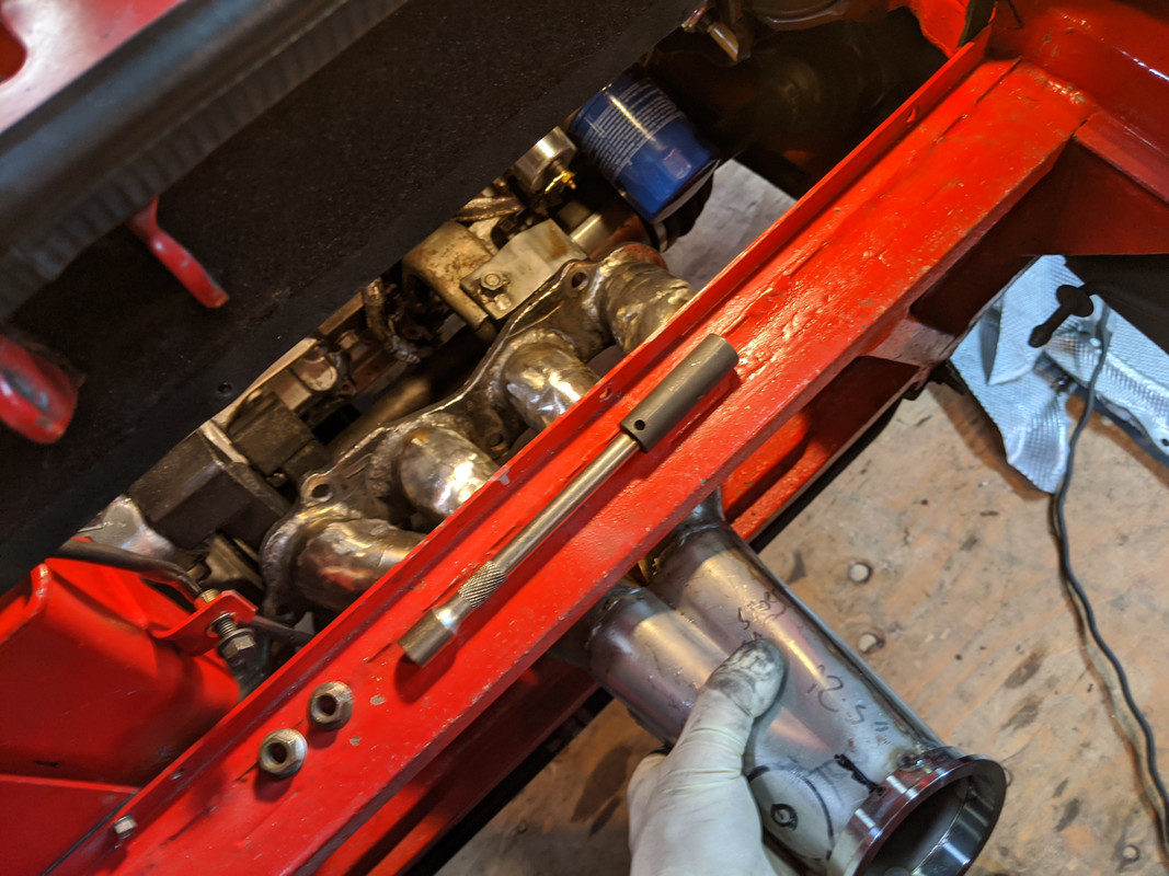 I cut up the Acura swaybar end links and used them to make the upper support brackets for the heat shield
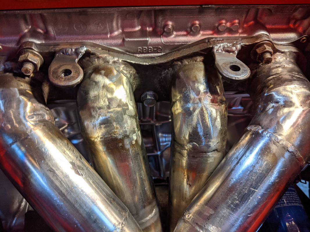
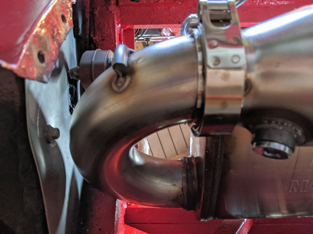
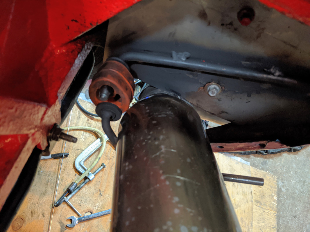
 drilled a new hole at the base, and transferred the isolating collar from the old lower section. Had to drill one side off & then silver solder it back in place
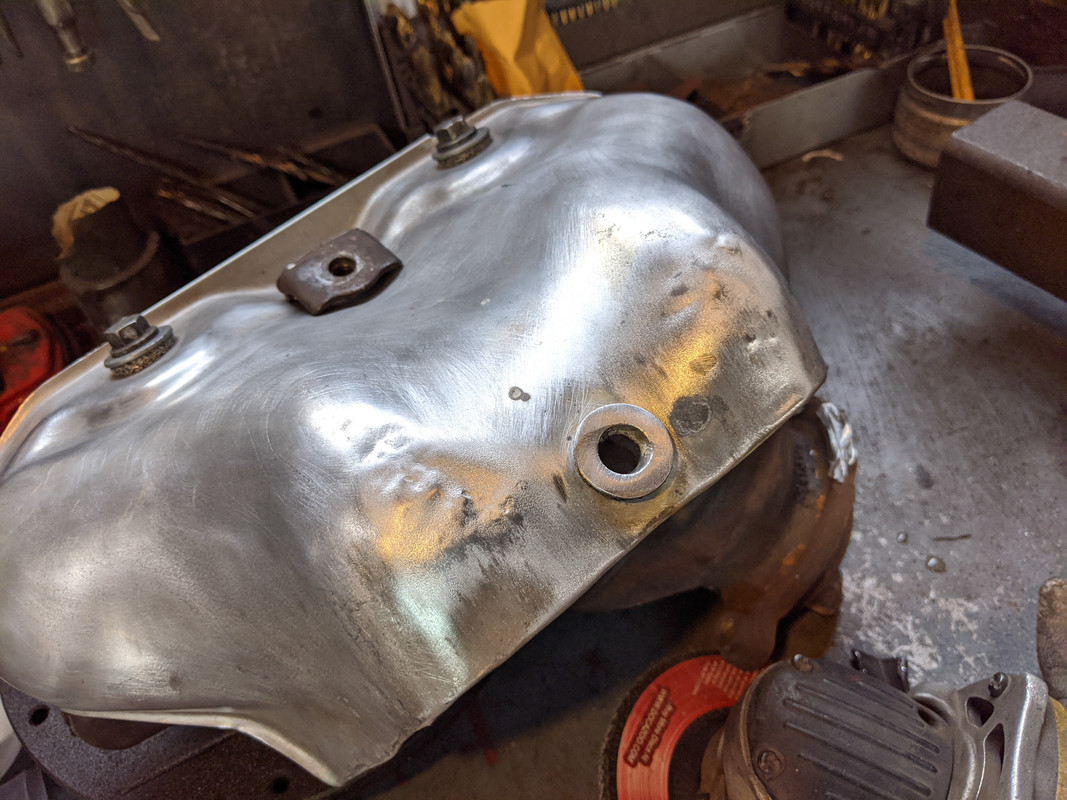 Have to make & weld a tab to the collector for that.Lastly, I started laying out the heat shield divider for crossmemember area. Probably going to drill & install a series of SS M4 rivnuts & use SS M4 hardware to secure it.
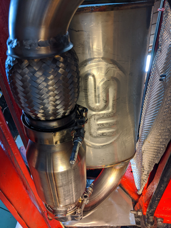
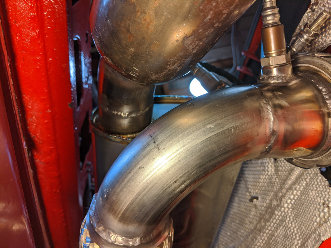
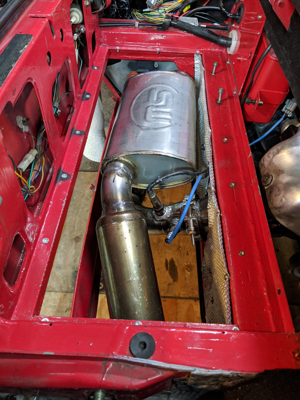
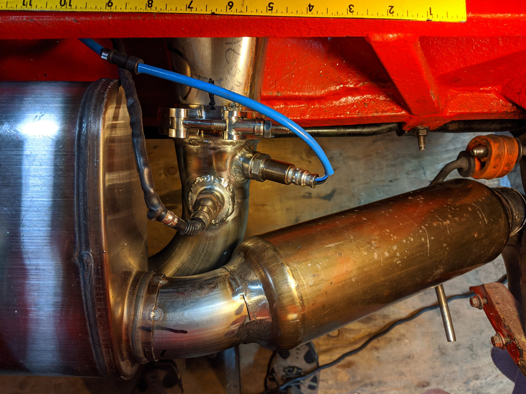
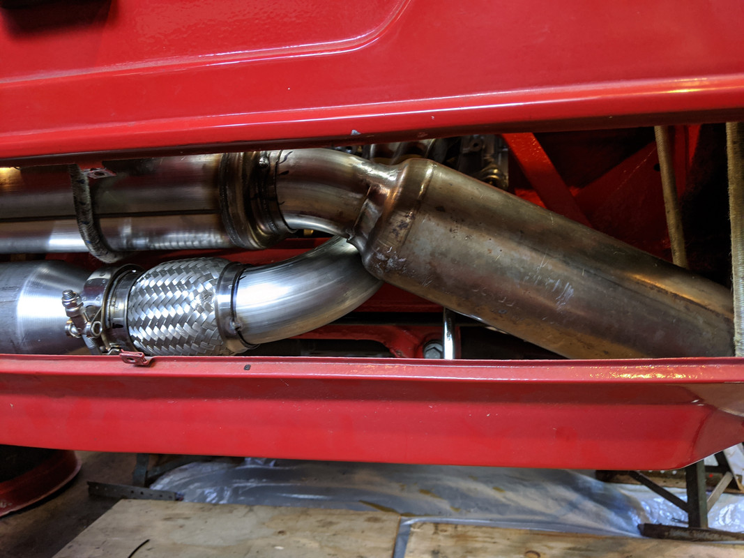
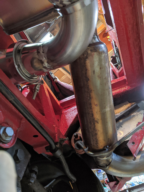
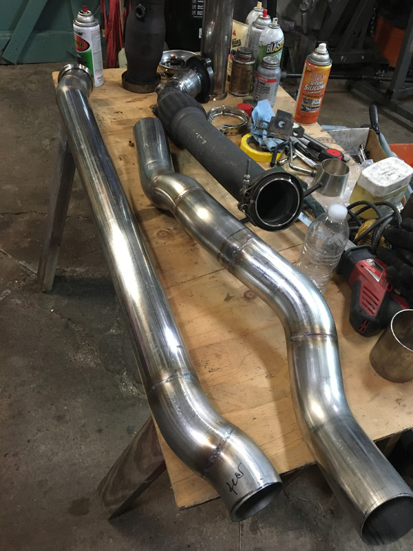
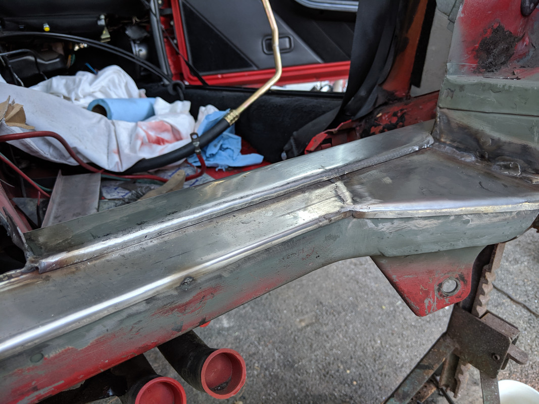
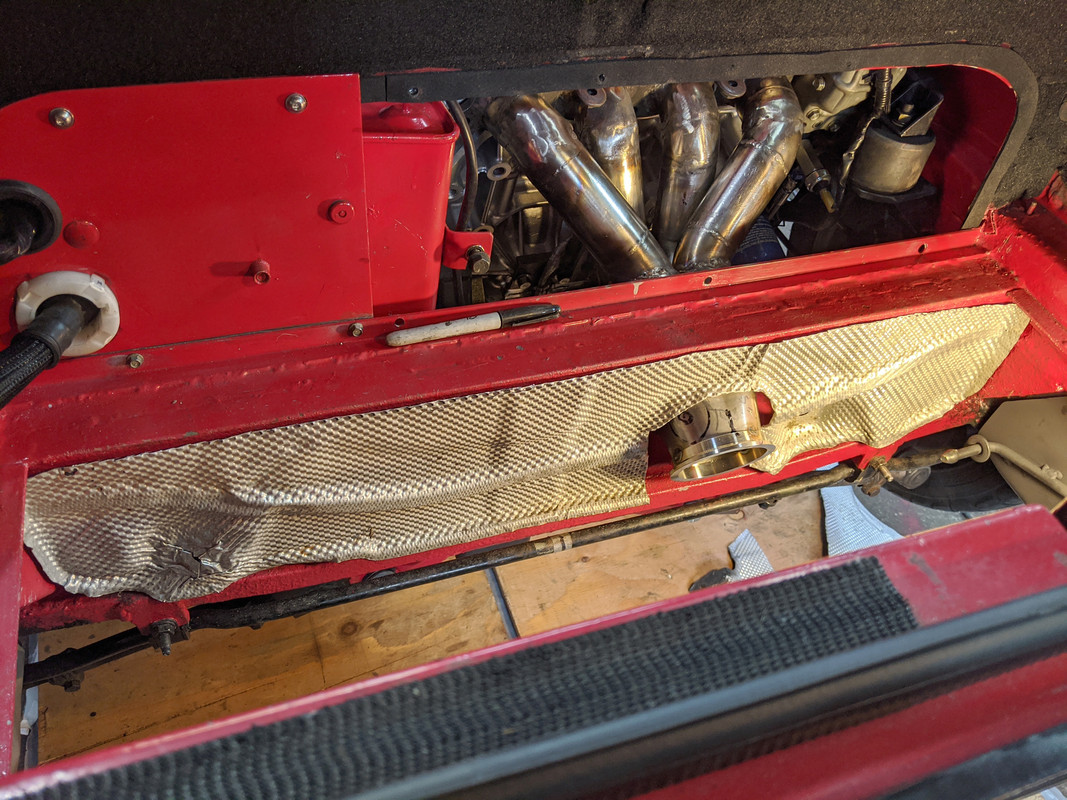 Stainless Works (2.5" 4"x8"x14" body chambered "Turbo") muffler arrived this morning. I had emailed them on Thursday when it didn't show as shipped (they said 2 weeks from time of order to ship), and they said they were a couple weeks behind (!) and that I might see it by New Years. I replied indicating I really wasn't happy with that outcome, and if they had indicated at the time of order that delivery could take around a month I may well have looked elsewhere. To their credit, I got a shipping notice Friday morning.Got it welded to the I/O pipes I had made for the Magnaflow muffler, with a little adaption due to the difference in muffler dimensions.Seem to have good clearances all around. I'll see what happens when it's operating on the road.
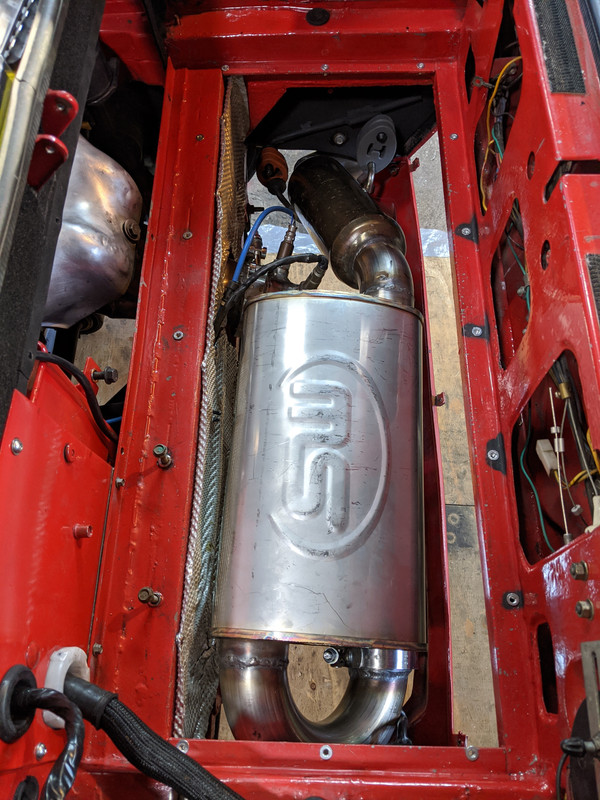
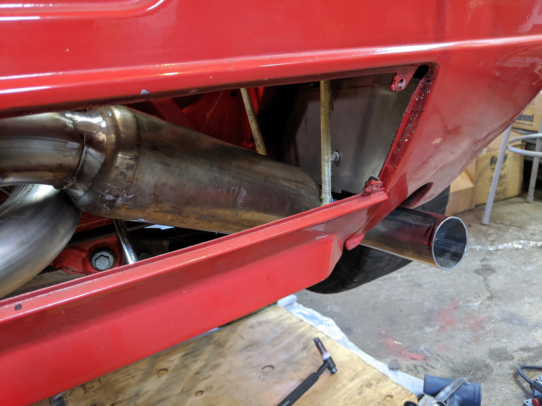
 Have to cut the tailpipe & add the RedTail SS tip. Not going to do that until the car is down & level so I can be sure the extension/offset is right.
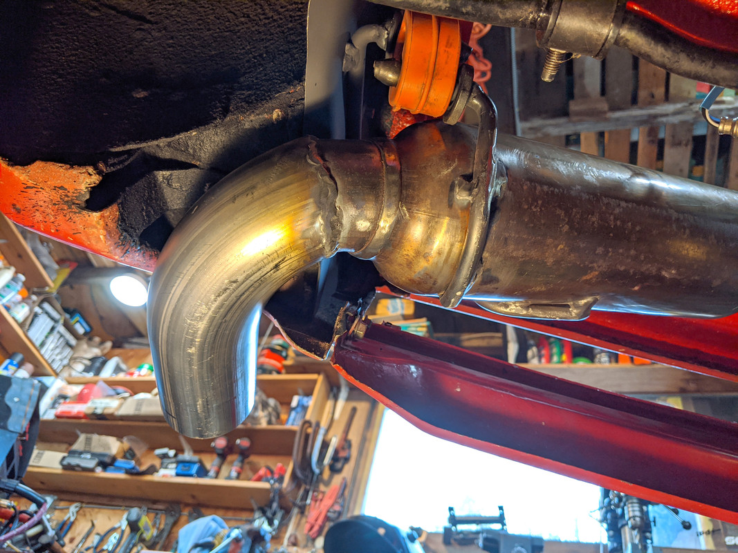
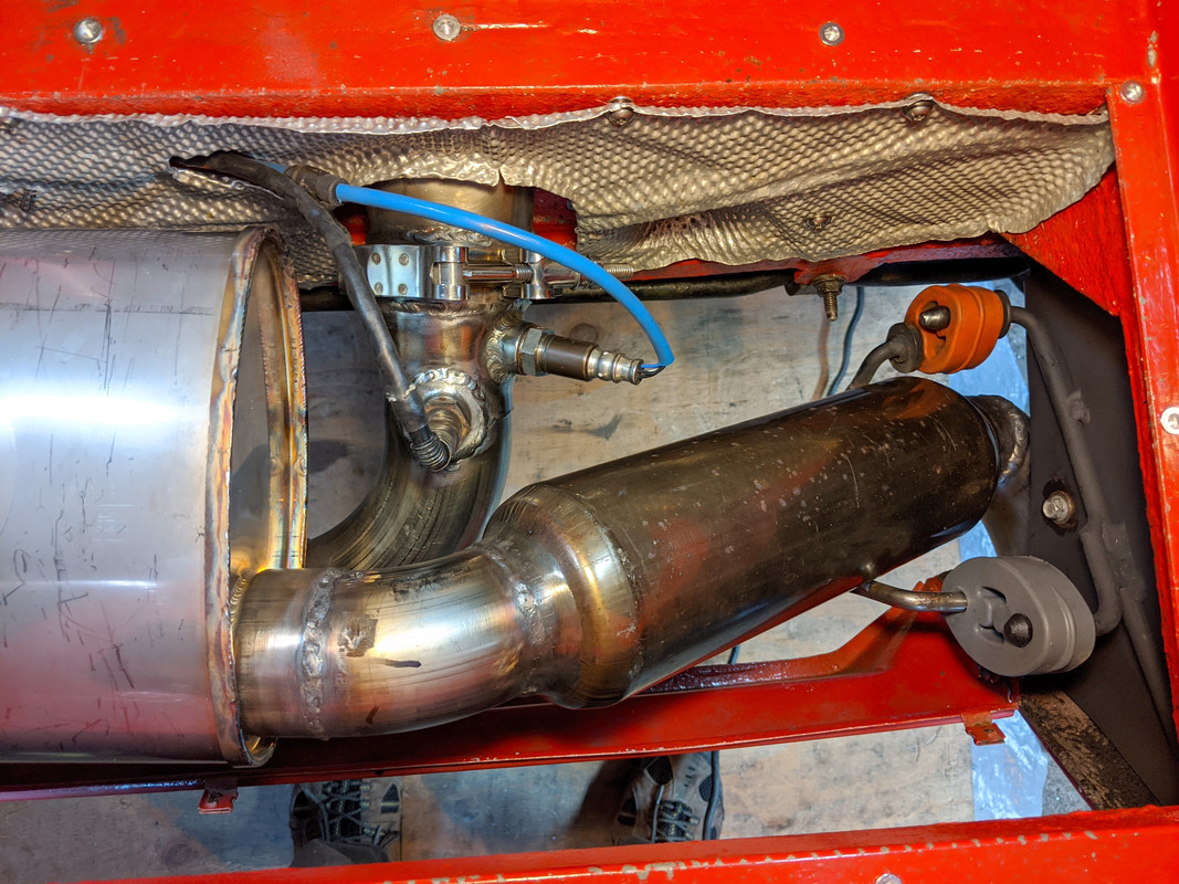
 the fact that it's not level is somewhat of a bother - however, not enough to compel me to rework it.
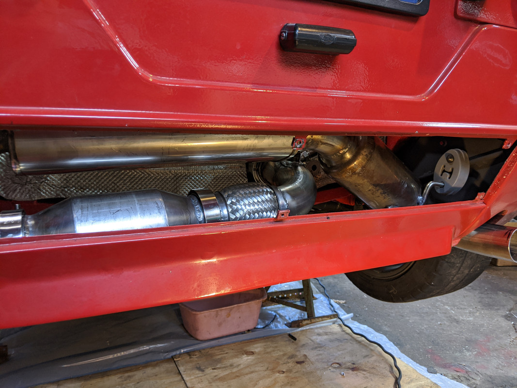
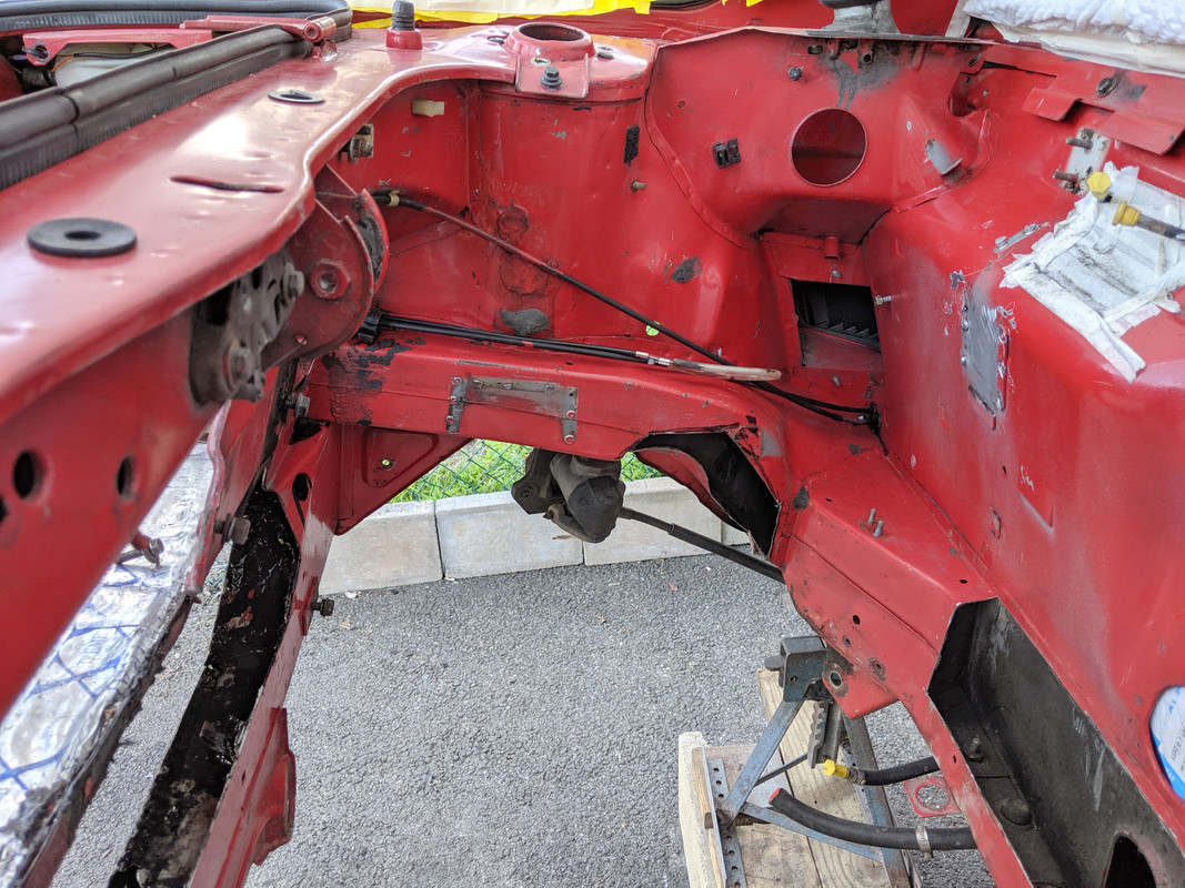
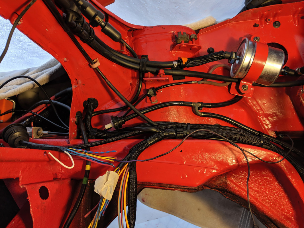
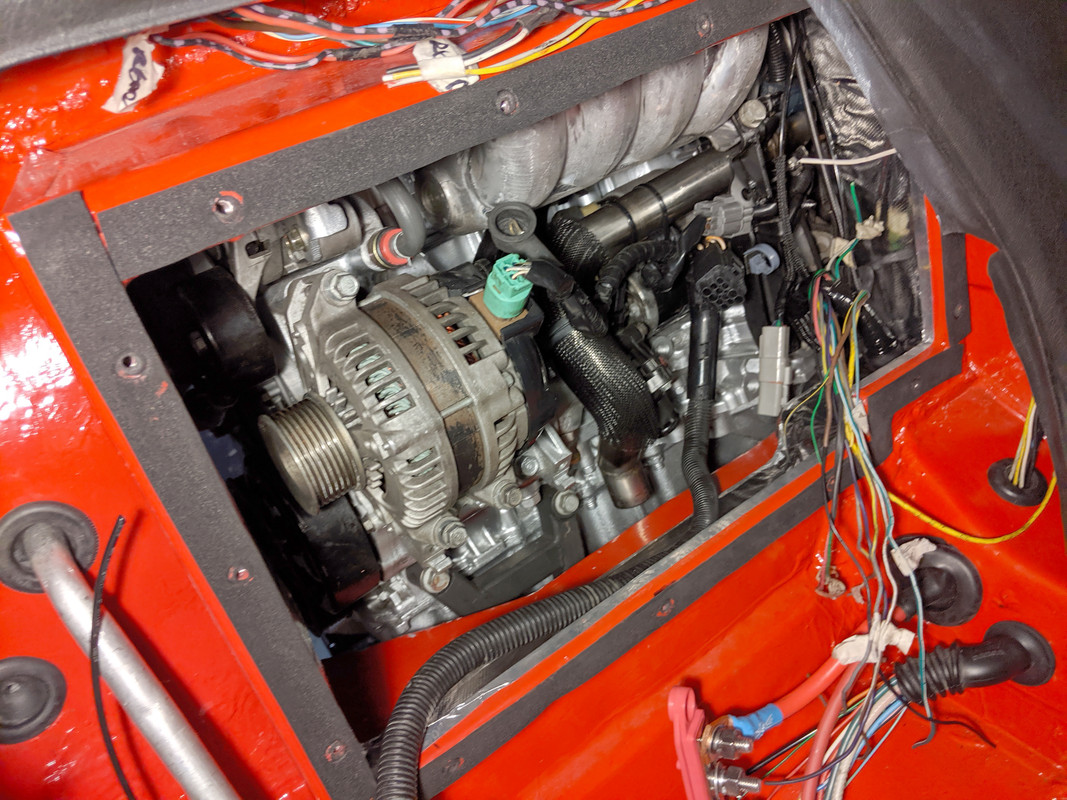
 With that out of the way , I started in on all the wiring that needs to happen. Took care of all the rear deck wiring
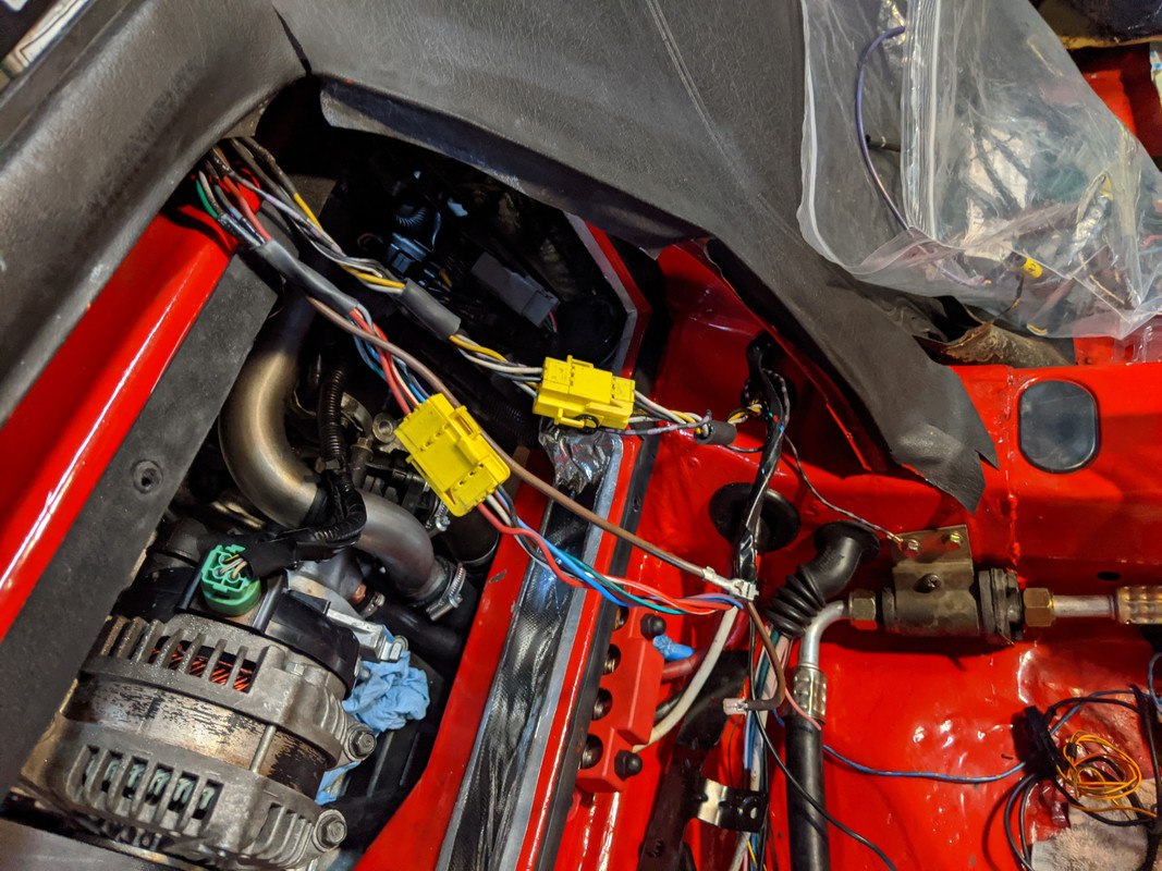 Next I'll do the relay wiring in here for the starter & bay fan, then move to the trunk for the ECU /EMS management wiring. Not really looking forward to that. Problem is I don't have a concrete plan on how best to lay it out.
 -
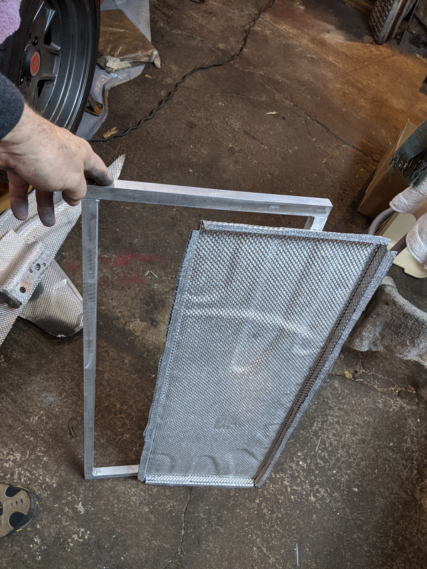
Worked on the heat shield / trunk floor framing today.Started with this heat shield from the S40 AWD
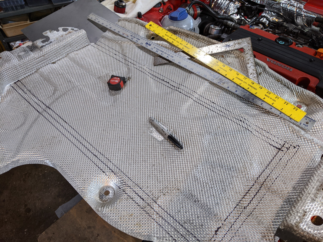 cut & folded to fit the opening, set upside-down here to use the opening to form the edges. Used the mallet to flatten the dimpled flanges, then pressed them bewtween two flats in the vice after this
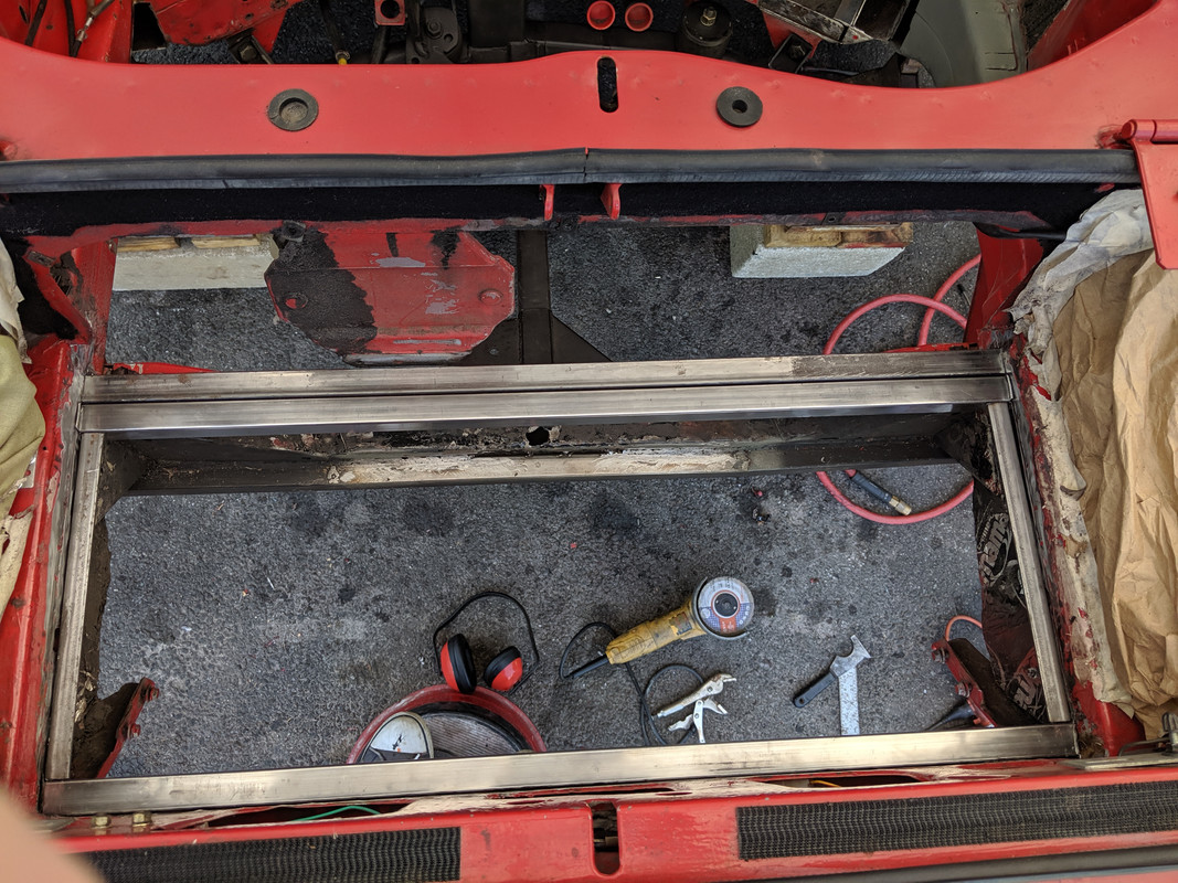
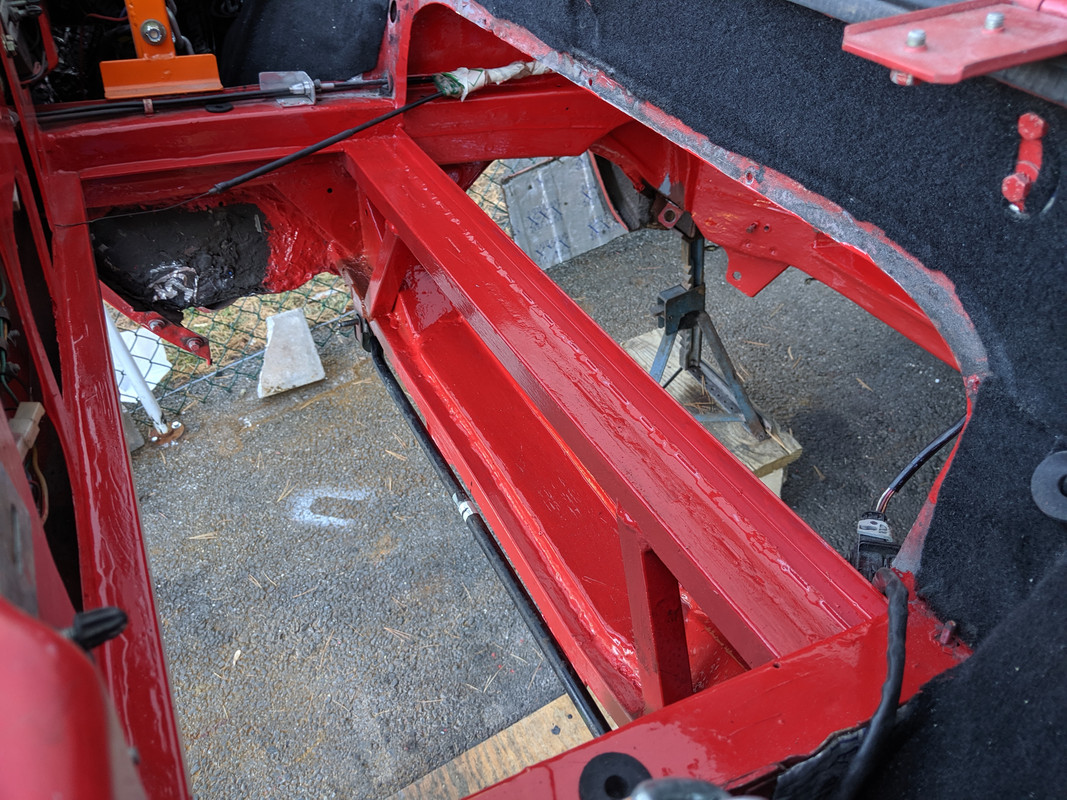
 Had to mull over what to do about the raised area - I decided to make a aluminum square tube frame to contain it, upon which the stainless steel floor pan will be attached.
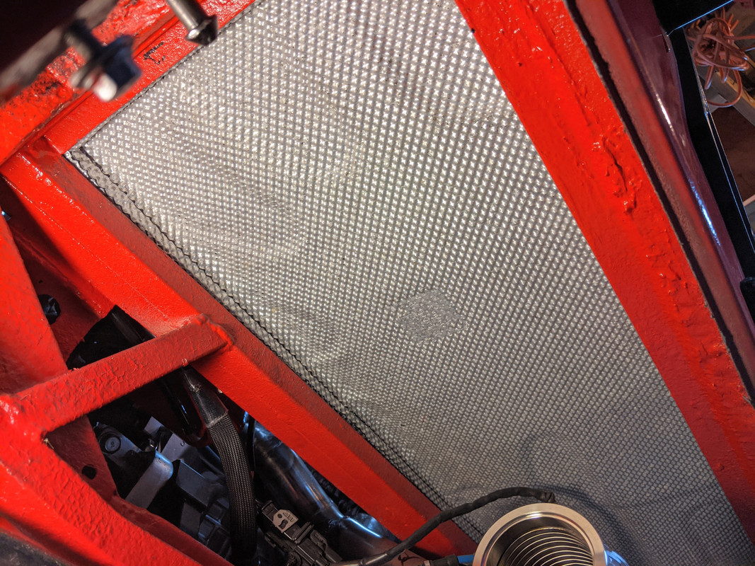
 air gap between the shield and panel
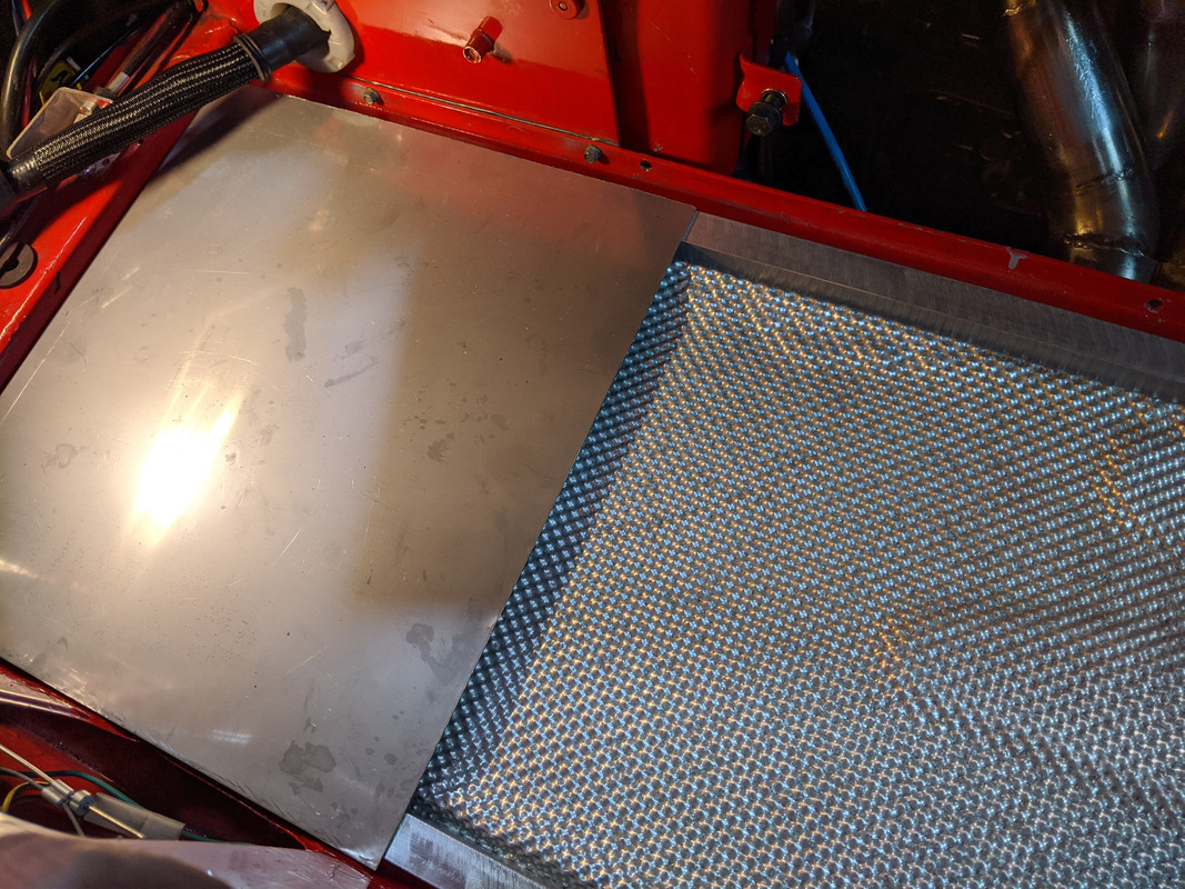 two sections will be cut & welded as one
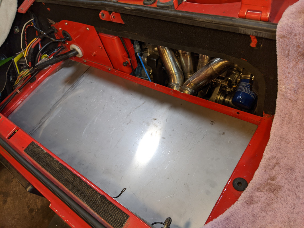 The excess from the shield should be sufficient to make a panel between the exhaust bay & engine bay
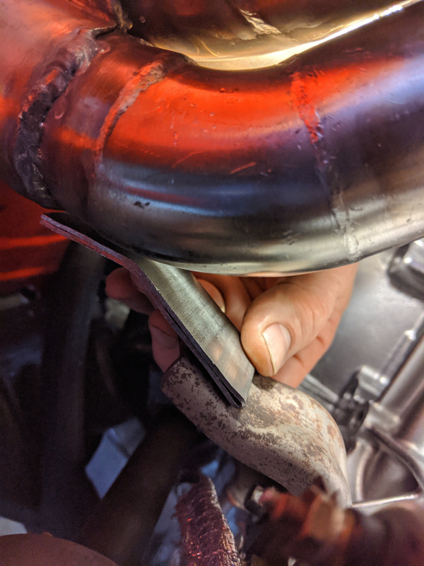
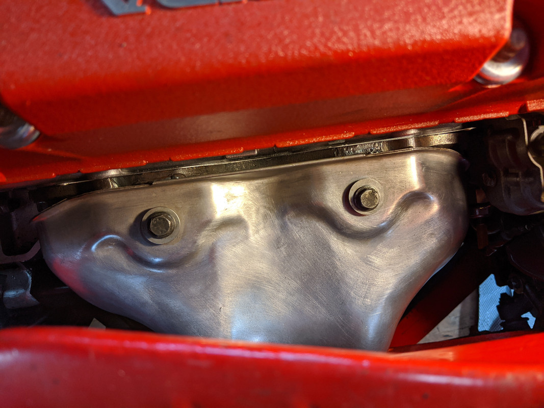
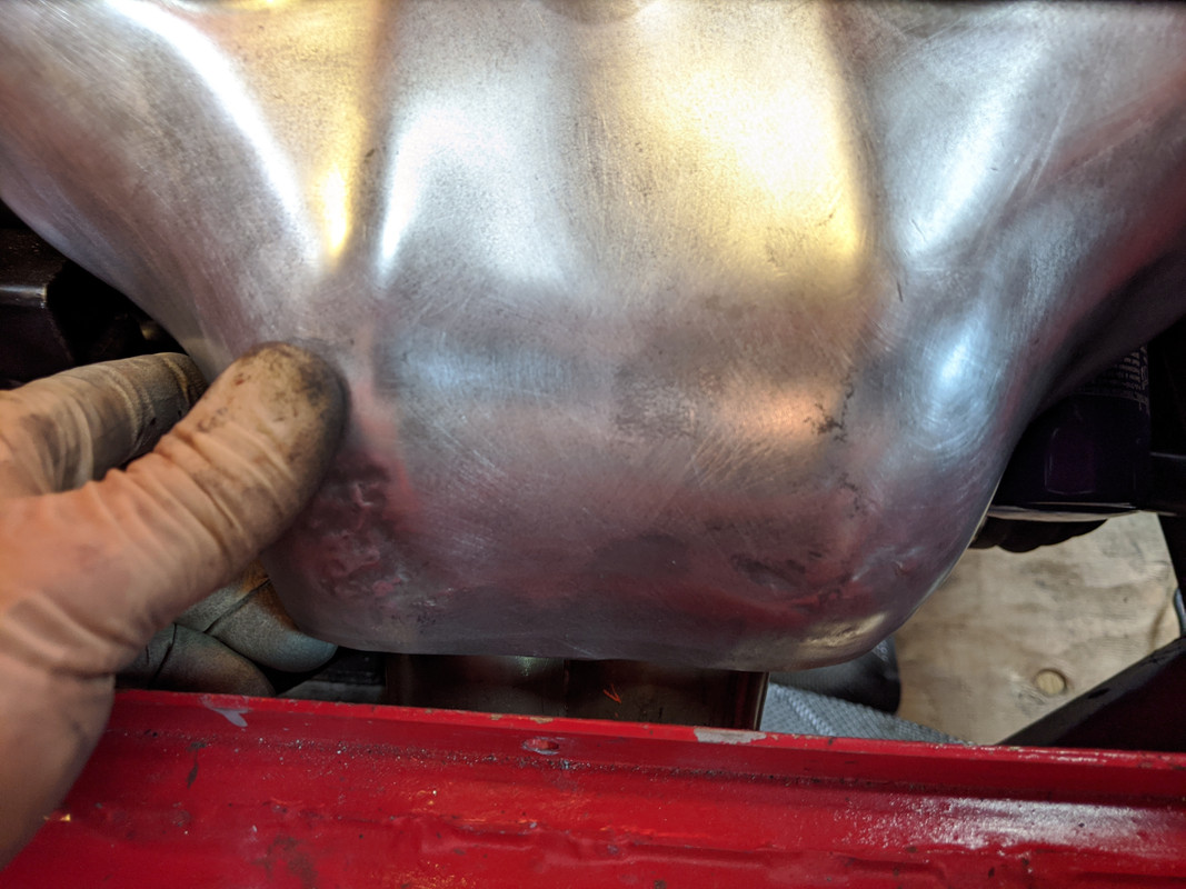
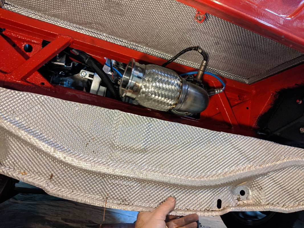 Whilst I was on a heatshield kick I cut the Honda manifold shield to fit the header
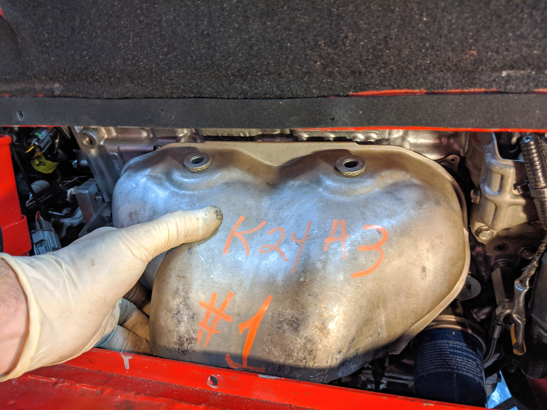 cut edge was folded in on itself to keep the two- layer integrity
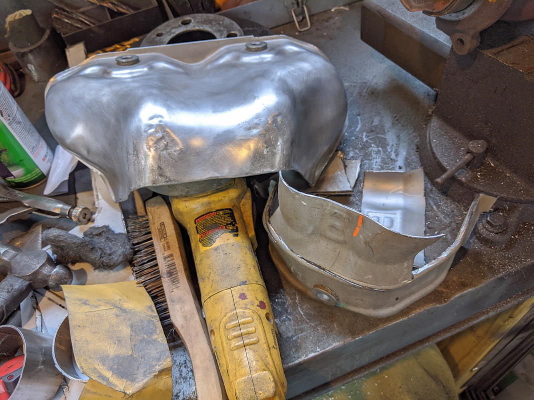 Have to weld tabs back on the manifold flange, and one by the collector to support it
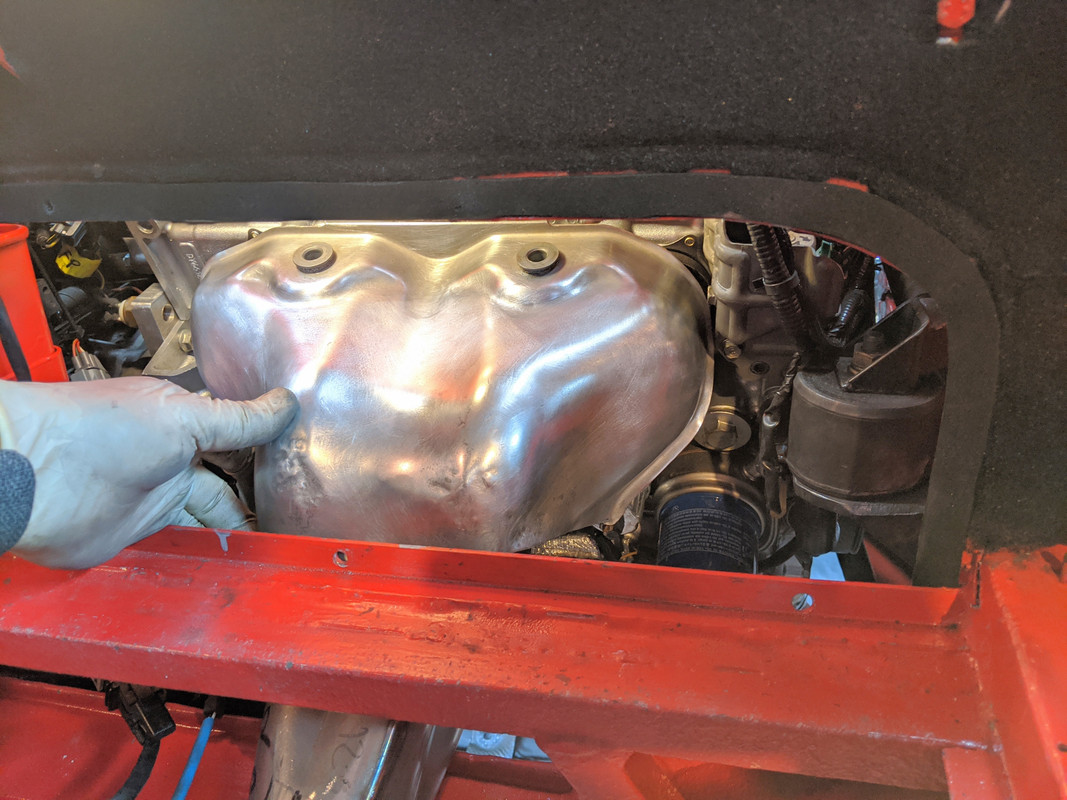
-
6
-
-
Still building the exhaust.

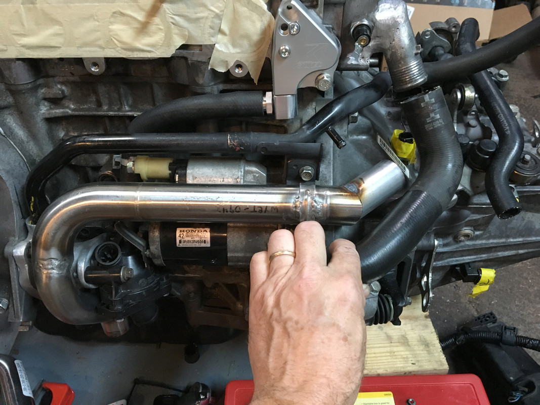
Finished up the water passage outlet, V70 t/stat neck
Finshed the adaptor housing and Volvo C30 t/stat housing install
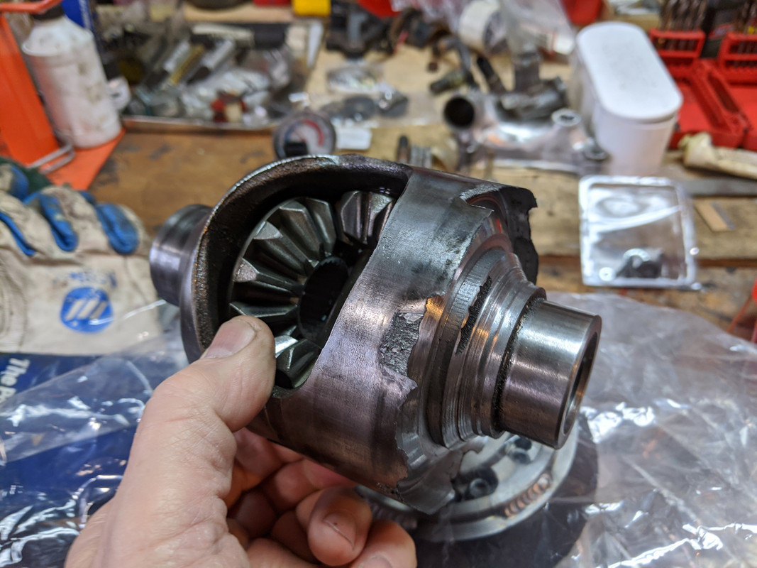
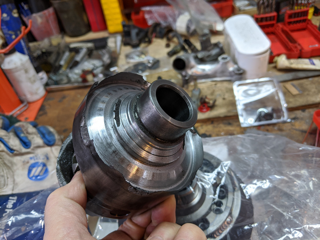
Quaife arrived for the C30 rear end. Waitng for the spare rear diff to chop up
-
1
-
-
On 11/12/2019 at 1:23 PM, Commander Riker said:
H! Man, nice work as always! I see the AWD is in your blood, sir.
Curious of your impressions of that AWD setup vs the old XC.
So.... We had some snow & ice, and I took it out to see what's what. With DSTC turned off, it's quite nice- but.... since these have no rear posi like the old P80's (cheap Ford bastards) the rear pushes right when it looses traction. I'm getting a Quaife QDF11J (AustinV70R on SwedeSpeed posted a howto). It is a fucked up install, since the ring gear is welded to the diff, but it needs to be done.
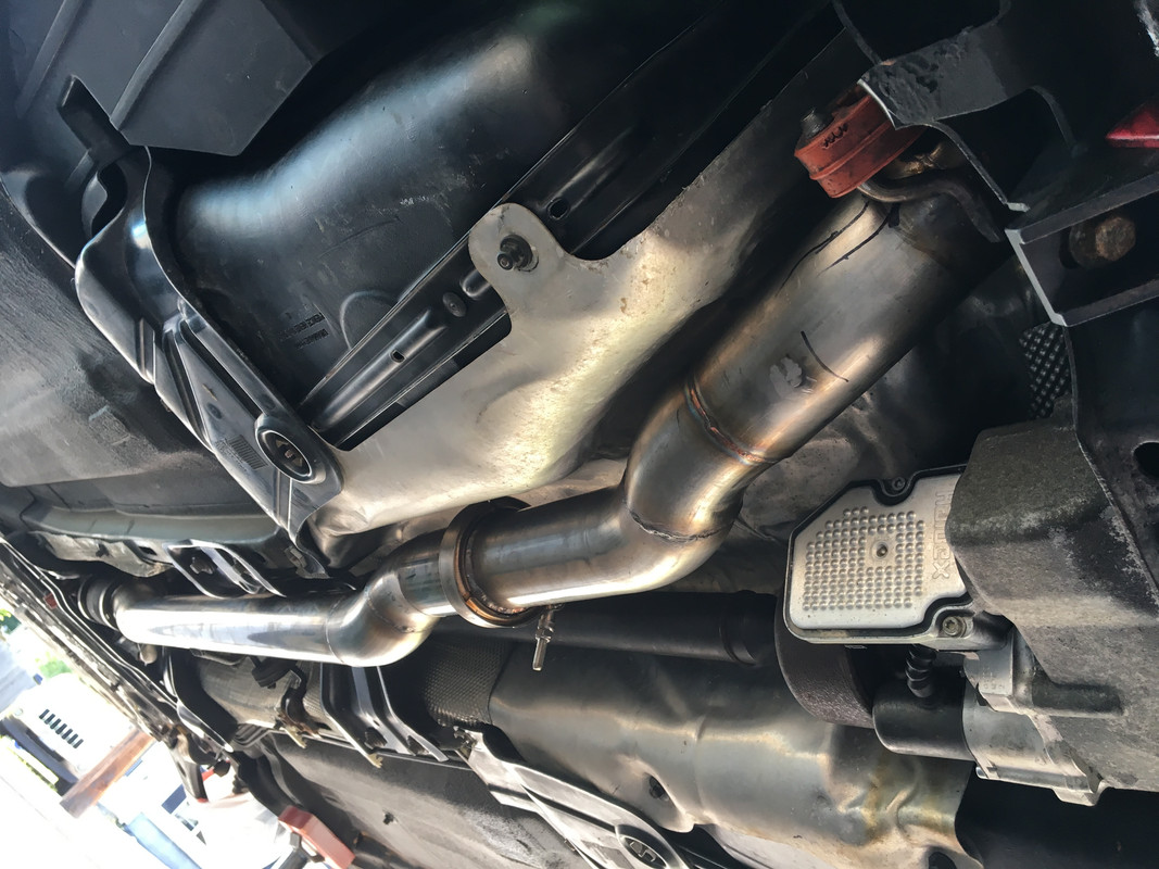
More work on the exhaust. Got the tailpipe/resonator laid out & tacked after some back & forth. Since the Magnaflow's are loud, I'm adding a resonator I cut off the S40 AWD exhaust :D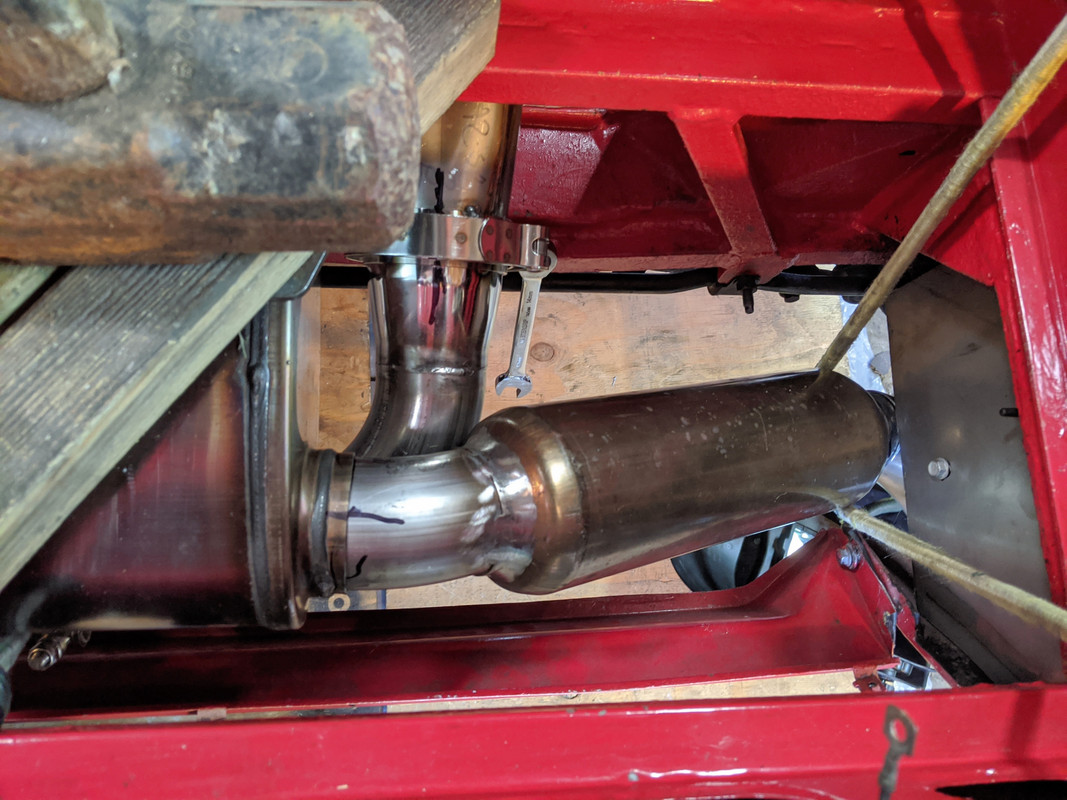
 After that, I started on the exhaust hanger setup - left side. Volvo hangers of course.
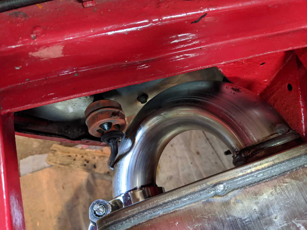 welded heavy wahers to the muffler pins to prevent the hanger walking sideways
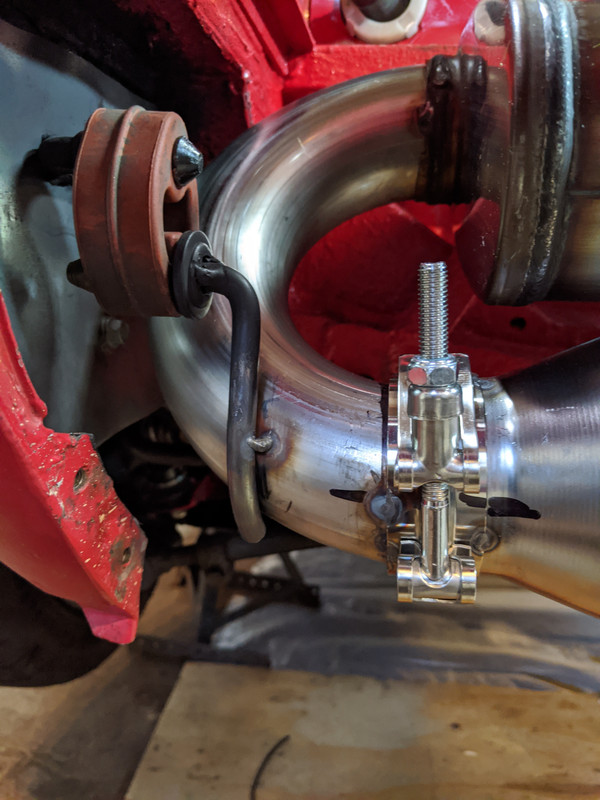
 Right side
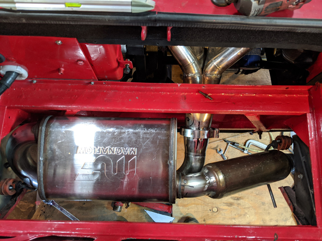
 Clearances all seem ok - has enough wiggle to not hit the chassis
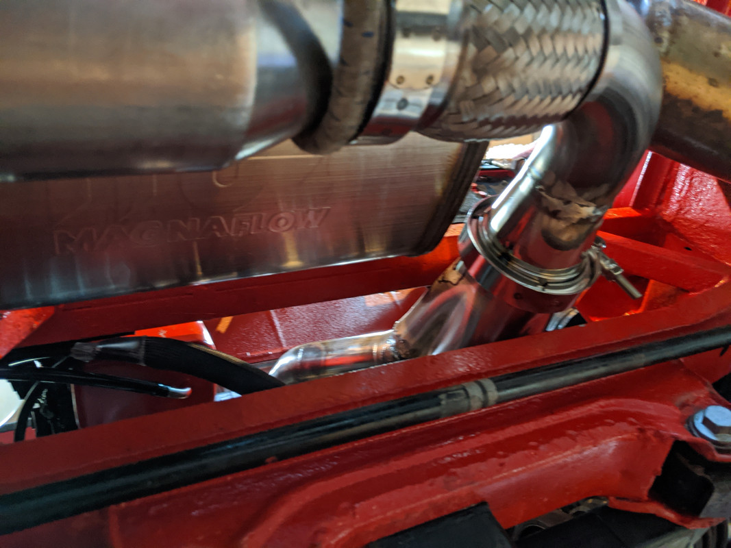 May need another hanger on the left front of the muffler or the rear side of the tailpipe, to keep the exhaust from rocking. The flex coupler allows a subtantial amount of tilt and twist.
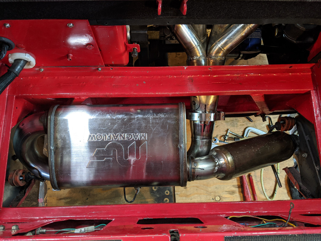 Not much clearance off the planned floor pan - may have to raise it
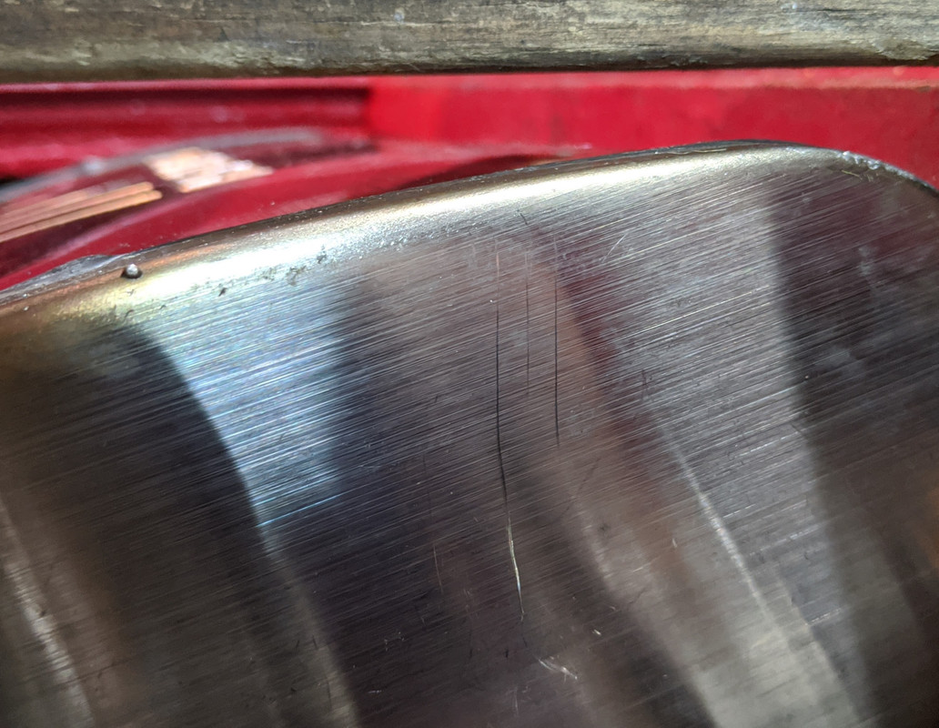 RedTail (2.5"x3.5"x4") L exhaust tip - will be going on the SW chambered muffler/open tailpipe setup. I'm not expecting to leave the Magnaflow on.
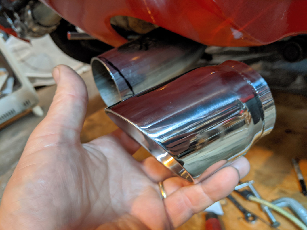 Have to figure out the header support - going to cut the ear off the old manifold, make an brace from that to the block or the rear MWB mount bracket to the header collector, whichever works.
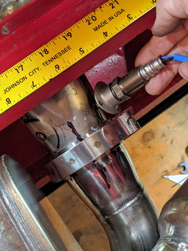
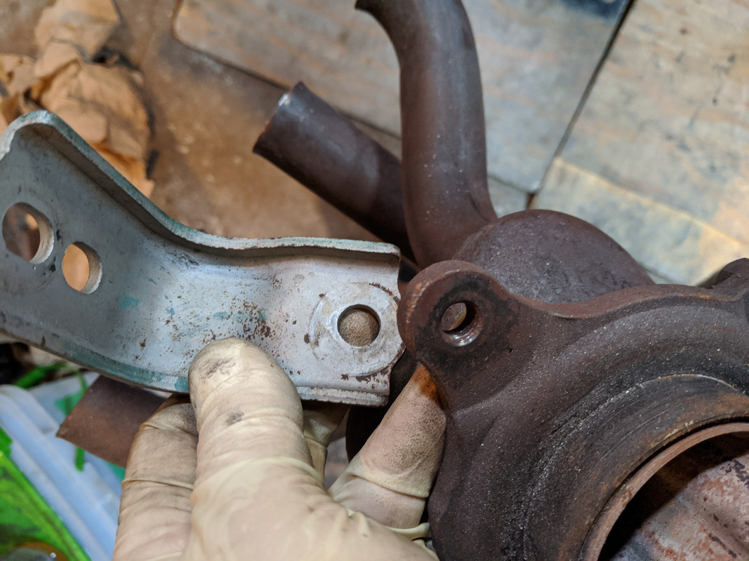 O2 sensor will go about here. Glad I didn't drill on the otherside where I was going to put it- that has insufficient clearance from the muffler now
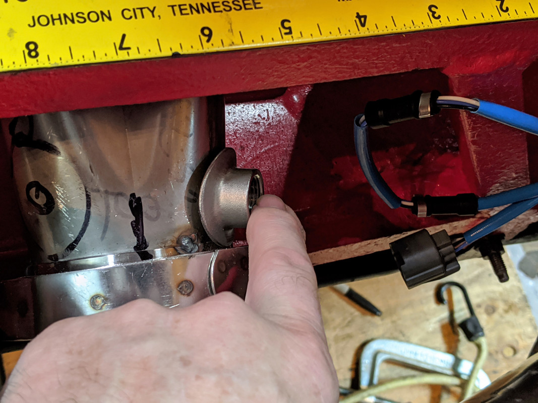
 WBO2 sensor will go around here, probably at 12 o'clock, if it will clear the floor OK, don't want it inline with the other O2
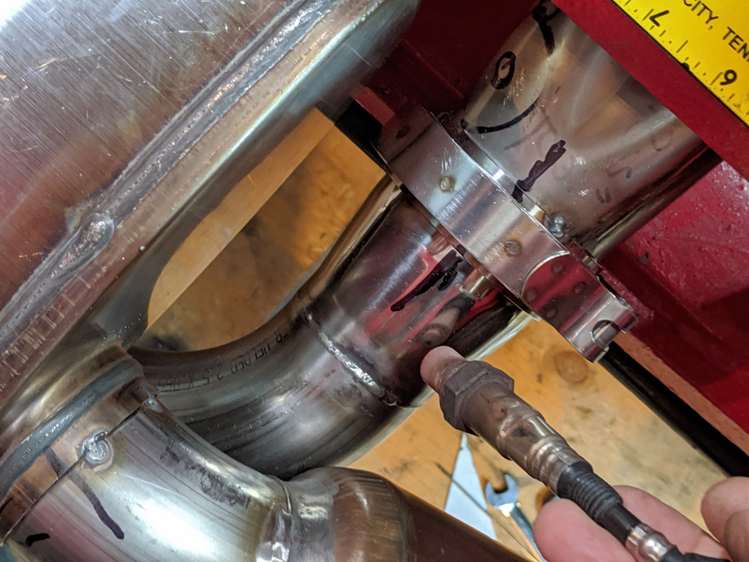 After that I started on the replacement water passage - cut the flanges off more cleanly than the previous. Heater pipe welded - that went better than last time also.
 Rad hose outlet ('00 V70 :D) will be something like this - have to remove the old one first to confirm placement
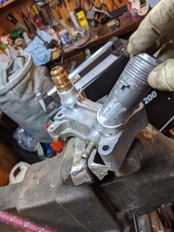
-
2
-
-
7 hours ago, Commander Riker said:
H! Man, nice work as always! I see the AWD is in your blood, sir.
Curious of your impressions of that AWD setup vs the old XC.
Thank you.
I haven't had bad weather to really check it out yet. The kinds of driving where the AWD shone was on the Parkway I commute on - it's 2 lane greenway divided, and floods really badly on the edge of the fast lane, perfect conditions for telling if the AWD is doing it's job.
In dry driving, it really makes a difference in higher speed ramp driving & long sweeping uphills where you can feel the rear pushing in a good way. I'm really happy with it. Annoying stuff is the software - I haven't got really agressive with it & you do have to remember to turn off the DSTC or you just get front wheel spin. Since I'm relying on Hilton for tuning, I really doubt I will ever go beyond the K16, but you never know....
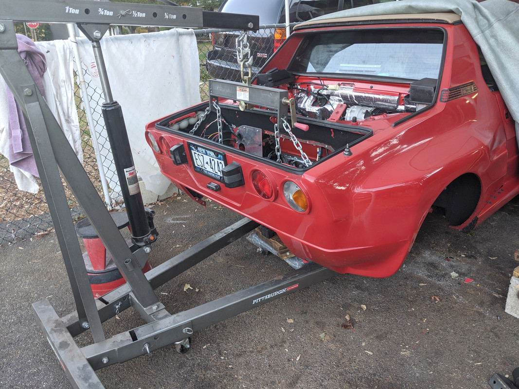
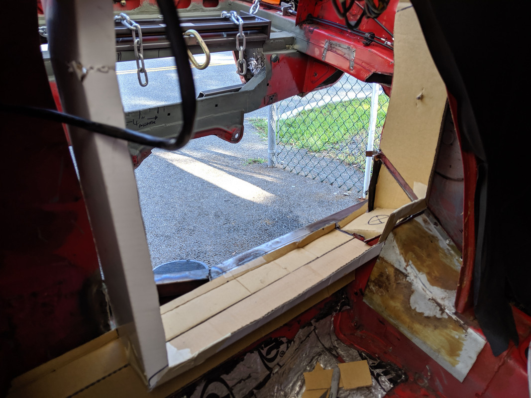
The X1/9 will be fun, since it's gonna be around 220WHP in a chassis that weighs maybe 2000lbs :)
The funky business with that is I have to raise & lower the car onto the drivetrain, no other way to install it.
-
1
-
2
-
-
AWD has been functional since June, using the Gen 3 controller, so I didn't go further with a Arduino controller. May still investigate that once I'm done with the X1/9 work. I'd add pics in the C30 thread I had, but it's archived & no one responded to my unlocking requests.


-
1
-
1
-
-
8 hours ago, ChristiaanW200 said:
The spine is different for the M66 right? What flywheel/clutch/pressure plate did you use?
Im going to do this mod on my 850R Aut. but with a diesel M66AWD. should keep 1st and 2nd the same, 3,4 and 5th slightly longer and an extra OD 6.
My previous 01 T4 S40 did 160km/h in 6th with a M66 mod
You can use the S60R complete clutch & flywheel setup. Or hybrid like oblark. Sounds like the diff axle splines are wrong on the Diesel M66 though...
-
On 1/29/2019 at 3:29 PM, Commander Riker said:
Oooooooooo neat. More info on the haldex controller please. That's going to be rad.
Unfortunately I can't give you much in specifics, I'm relying on someone who knows WTF they are doing to help me with schematics. Another C30Crew member who did the AWD conversion & has the non-functioning Haldex issue found this thread. That's what we are working off. That, and a couple videos to figure out wiring from:
-
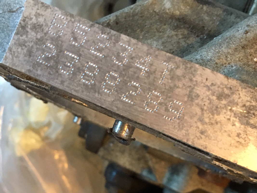
Pretty sure I still have a couple. I can check. Do you have the PN/ Casting # off yours for reference? Splines are good on mine.
-
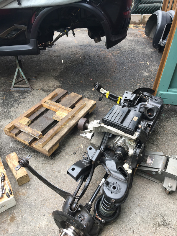
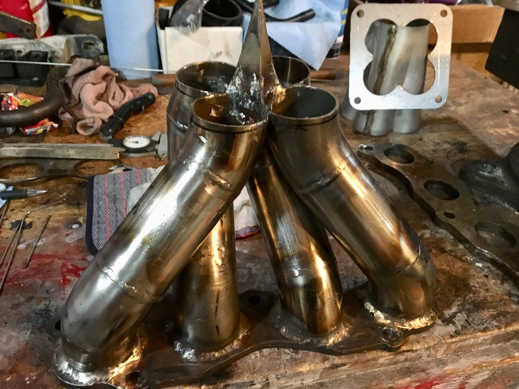
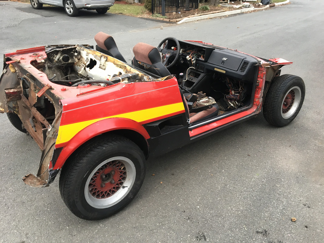
Worked on the finish welds for the intake, built most of the header, and chopped up the parts car to make the test bed for K24 motor & custom dash projects

Cone engineering merge collector & collector
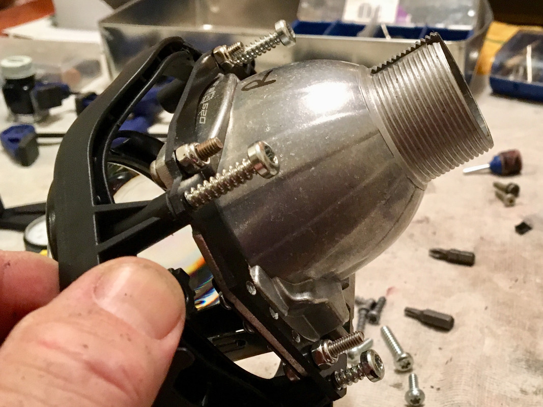
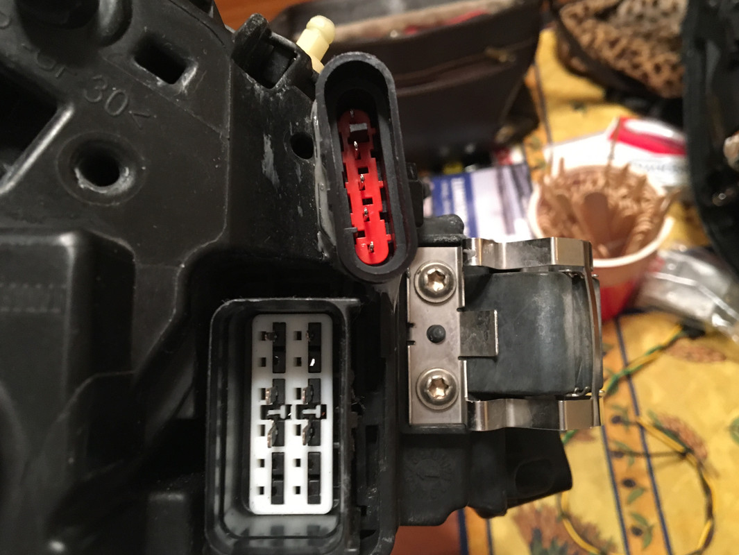
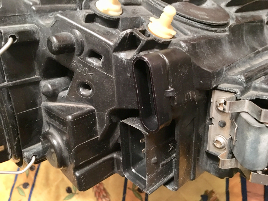
Blacked out the headlamps on the C30, and fitting Morimoto Bi-Xenon projectors. Just waiting for the SKBOWE kits for final install
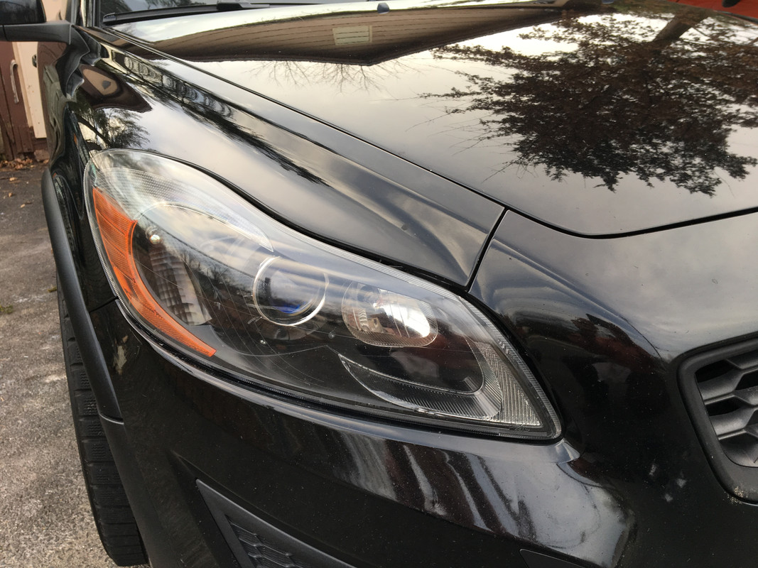
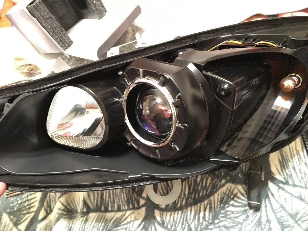
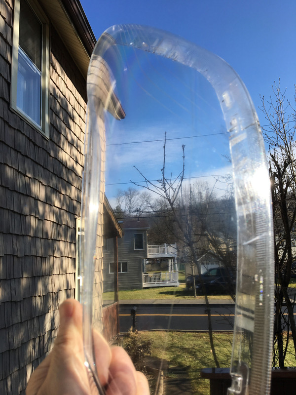
wetsanded and polished the lenses, not perfect but much better
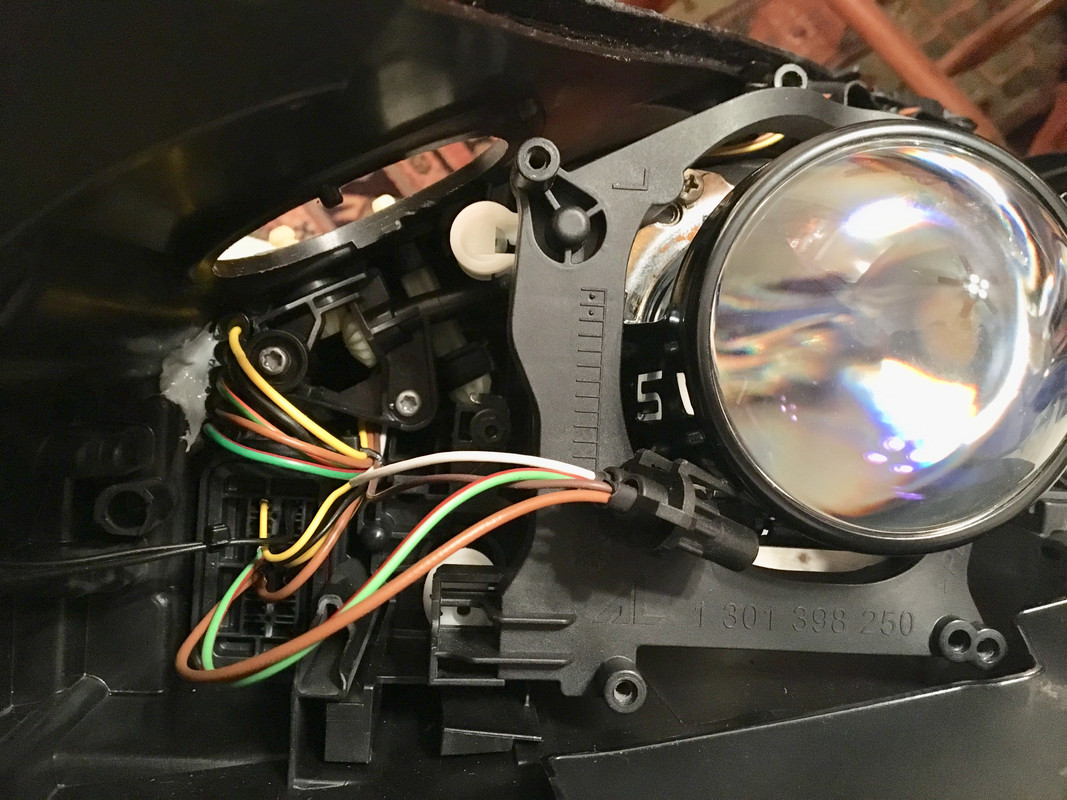
Modified housing & added extra socket so all wiring goes out with factory look
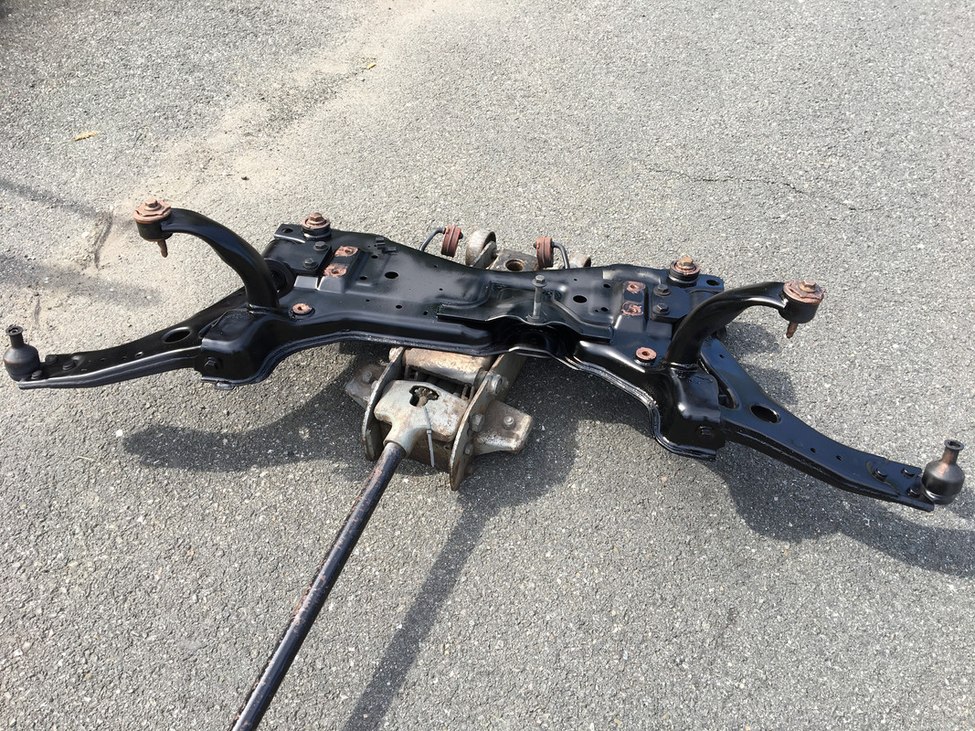
Also gathering parts for the AWD conversion.
M66 AWD with Quaife getting ready
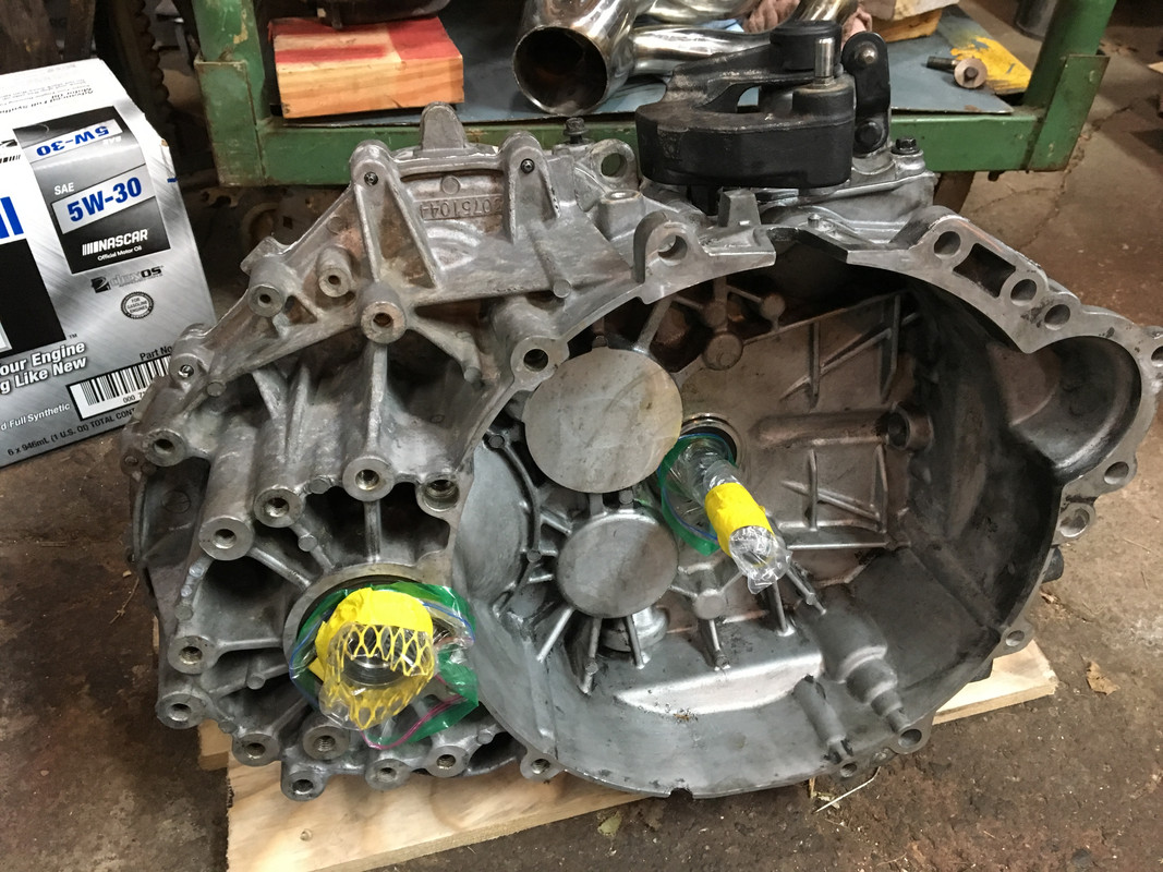
Broke down & bought the Volvo left axle puller.
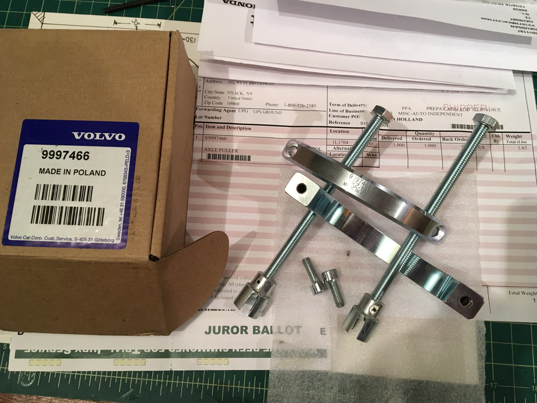
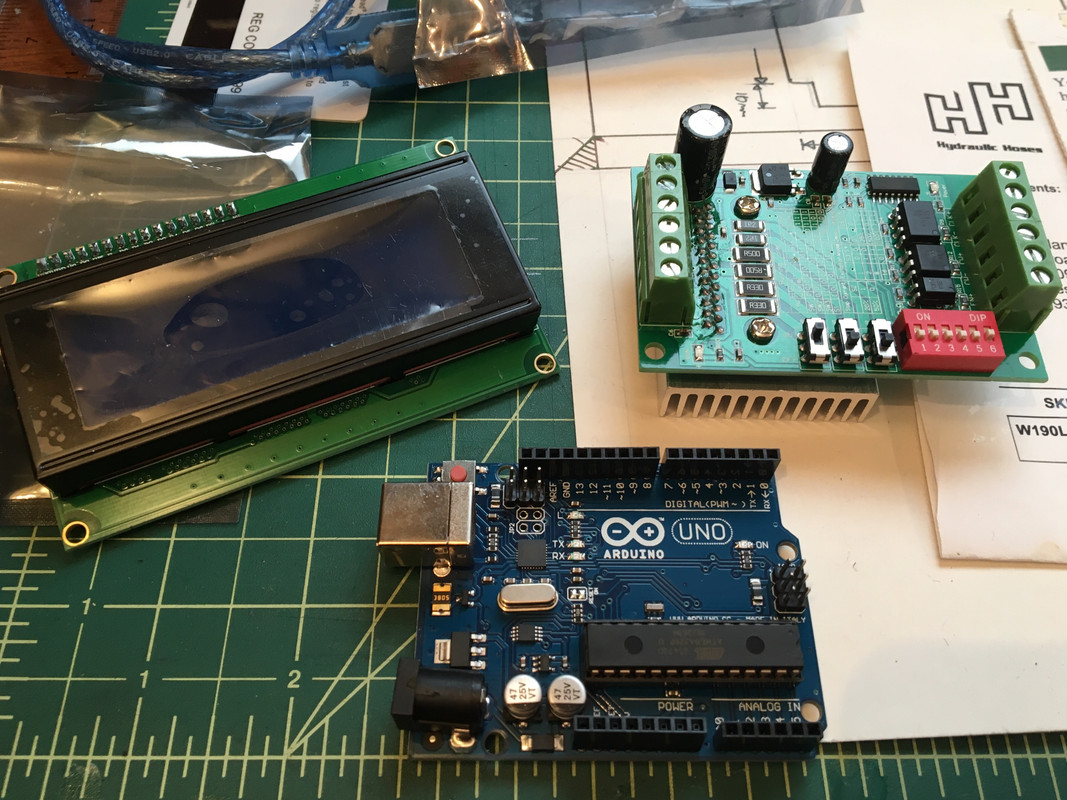
Going to build a Haldex controller, in the probable event the Gen3 controller doesn't work as it should
-
3
-
-
6 hours ago, BlackT5 said:
2000R Angle gear wont work with M66 unless you can find a passenger axle that has the seal in the correct place. 2000R passenger axle won't fit M66
You know, I forgot about the axle :D - doesn't the '00 XC axle fit though? The R axle has different diff splines, that was the issue you had, correct?
-
7 hours ago, Andzey said:
So the '00 DP only fits with '00 AG, while '99 DP works fine with both 99 and 00?
Because the '99 AG sits further to the right, and the '00 DP & AG are offset further to the left so will hit the '99 AG unless modified.
-
Looks good!
Side note, you could use a '00 AG in a '99, you'd just need the '00 right axle. Doesn't work the other way around (without additional mod), since the DP would be in the way.
-
Fixing Pic links
-
3
-
-
On 12/26/2018 at 4:18 PM, Simply Volvo said:
Well, it’s been quite a while but this thread and project has not been forgotten.
I finished up my masters degree in computer science last week and am on a much needed vacation. If your curious you can read about my thesis here https://web.wpi.edu/Pubs/ETD/Available/etd-121418-102453/ the link to the full write up is at the bottom.
Starting work soon and will finally have 12/12 months of the year to work on this car instead of 3/12 like I’ve had for the past 5 years while I was working on my bachelors and masters.
~Matt
Congratulations, Matt!
-
3 hours ago, BlackT5 said:
That's going to be a job a half!
If only you had left your photobucket images, they would now still show.. just with the watermark
Yeah, ain't that a bitch :(
-
Working on fixing the pics - starting from the beginning.
-
3
-
-
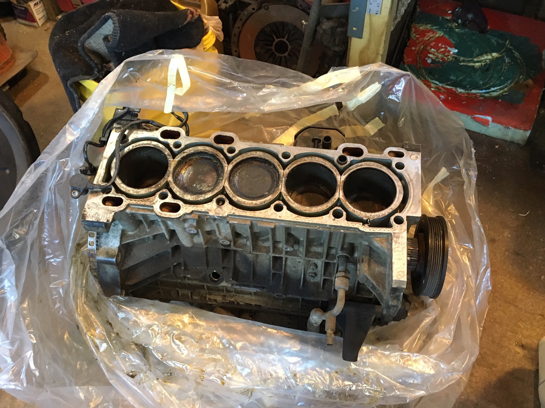
On 12/3/2018 at 10:02 PM, andyb5 said:
Well, recent events may lead to an unexpected change of direction for this project.
The engine has developed a ticking sound from the engine. I first noticed the sound occasionally appearing late last week, and it has begun to become more constant. I'll do some more investigation/documentation to confirm, but right now I'm 99% sure one of the rod bearings is toast

I'm now on the hunt for a replacement engine. As much as I'd like to build a fresh bottom end, budget and time constraints mean that won't happen at this time. My ideal replacement for this 99 B5234T8 would be a B5234T9 from an 03/04 C70, which is nearly the same engine, with a number of small incremental improvements that should help make it a bit more reliable and develop a bit more power when compared to the older engine. I did consider a number of other options, but ultimately would like to stick with an 81mm bore block for the increased integrity of the block that offers when compared to an 83mm bore. The 147mm rods used on the later motors theoretically offer a small improvement in higher-RPM breathing than the 139.5mm rods in the 99 B5234T8 that I have now.
As of now, with limited diagnostics performed, I DO NOT believe it to be related to Steve's tune, and would like to remind anyone who thinks otherwise that I ran a tune from Steve for over 25,000 miles on this engine in my old car without any issues. When you consider that this motor now has close to 240,000 miles, still has the original oil pan o-rings, and has had several brushes with low oil level/pressure throughout the nearly 90,000 miles of hard driving in 2 different chassis since I purchased the 99 R it came in almost exactly 7 years ago, it is my hypothesis that the level of wear that the engine was able to tolerate before exhibiting a major symptom of imminent failure has finally been reached.
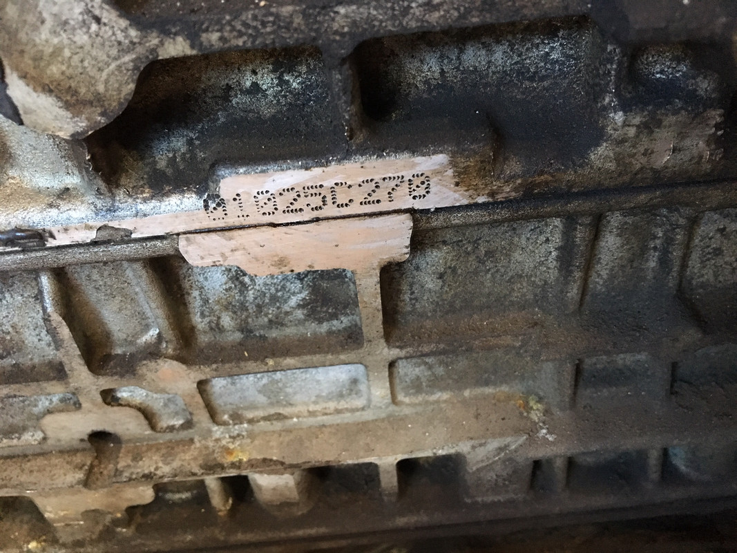
I have a B5234T short block from C70 of that vintage :D Bought from Maciek back then. Don't recall mileage precisely , my recollection is that it was 75K range.
coated bores with grease 3 years ago when I stashed it after parting out the XR - I was going to use it.
-
2 hours ago, apeacock said:
Are you brazing the joints or is it some flavor of welding?
Messy TIG. I don't have clean seams / junctions to weld here, and the thickness is on the upside of my machine's AMP rating, that's my rationale for the fugly welds, anyway :D
-
Bumping in case of Archive feature :D
Any new developments?
-
21 hours ago, andyb5 said:
Glad to see you’re still finding new and innovative ways to use Volvo parts for custom purposes. That seems like the thermostat housings worked out pretty nicely. What was involved with the intake manifold modifications? Looks a fair bit different than the stock Honda manifold..!
If i had to guess, you’ll end up adding some boost to the K24 at some point down the road
 Since the K24 flows so nicely in NA form, my understanding is they respond really well to boost too.
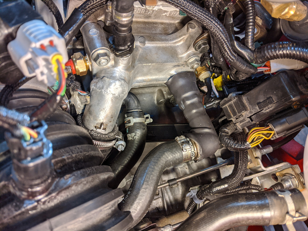
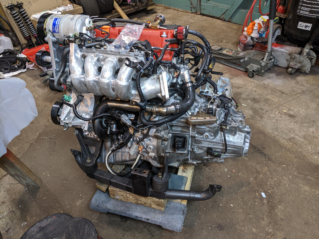
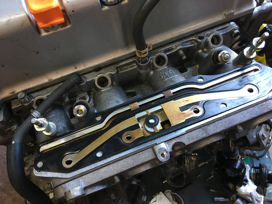
The K24 has a longer runner 2-part (RBB) manifold - lower part with plenum visible here. Built for low & mid range torque, of which it has plenty. I want to maintain that. Some people swap a K20 head (and cams setup), PRB intake & run 9K redline to get max HP. I'd rather have the torque where I can use it for DD. Since the car only weighs 2000lbs (maybe less with all the steel I cut away), the power -to-weight ratio is pretty decent even with the stock 210BHP.
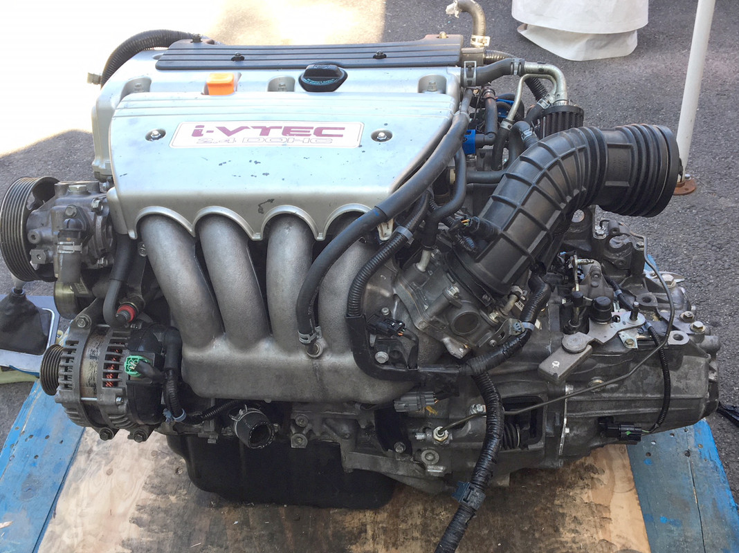
The upper half has a sophisticated CC breather setup, akin to the RNC, just not at the head. I want to save that. This runner section is about 6". No room to add a large enough plenum directly to this, so I needed to tuck the plenum underneath. Overall length is just a little shorter than the stock arrangement.
-
1
-
-
18 hours ago, andyb5 said:
The good news is photobucket is back up, albeit with a watermark on the photos now. If your account is still there, the photos will display like they used to in your posts.
Nice work on the X1/9 body kit!! Love how it transformed the car

I have a feeling that once you start playing with the K24 you’ll forget all about modifying Volvo’s...
Adding pics back into the thread, working backwards. My PB account is gone, along with any pics that were left in it.
Hello Andy! I'm going to be using K-Tuner to set it up, so DTR I could add a turbo, etc., if I choose. The AWD dyno guy I used to use for the XR is a Honda Tuner, so he can dyno tune the K24 when I get to that place. I did have to make a major revison to the RBB intake in order for the TB setup to work.
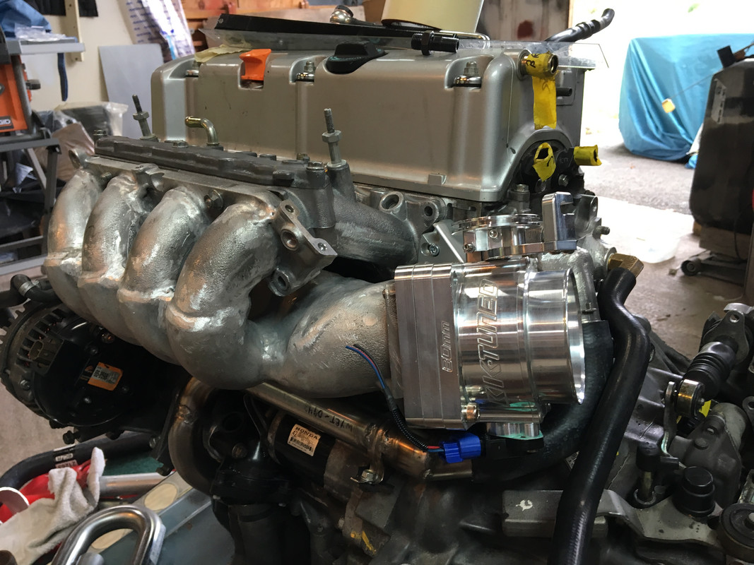
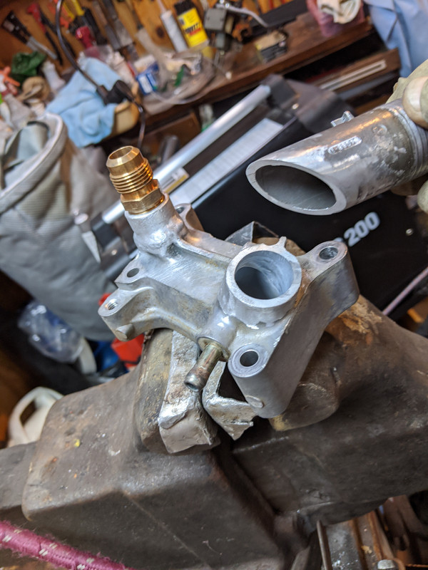
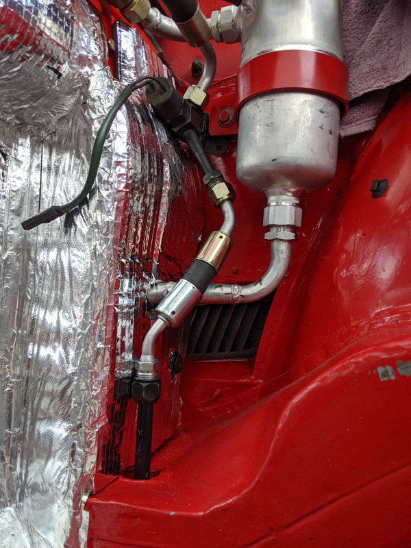
Fabricating water pipes to fit the X1/9 body side cooling setup - Using a C30 T/stat housing (bottom left) off a custom adaptor and a V70 T/stat cover welded to the upper housing (upper right) to replace the Honda bits...
-
2
-
1998 V70 Xc From The Beginning... to the End
in Show Room
Posted